Model Railway Track
(The do's and don’ts)
Contents:
What is Gauge? What is Loading Gauge? Track Layout Design -
What model railway track should I buy and what should
I avoid?
-
PECO Vs Hornby
How to fix points? What points are best? Replacing Hornby standard points with PECO points What layouts don’t work and why? What is an Isolating Section? Electrofrogs Vs Insulfrogs How does DCC (Digital Command Control) change your track design? PECO, Hornby, Bachmann Track Conversion Table
What is Gauge?
Gauge is the name given to the distance between the rails. "OO" gauge which
this site mainly deals with (although most is compatible with HO) scale is
1:76. The track that "OO" gauge uses is not true to the scale of the rolling
stock, with the track being smaller than it should be. "HO" gauge (Commonly
modelled on the continent) uses the same sized track, but smaller (true
scale) rolling stock.
There are other gauges such as "N" gauge which is very small,
and "O" Gauge which is very large.
[back to the top]
What is Loading Gauge?
Loading gauge designates the space required either side and
above the track that needs to be clear, so that either the locomotive and
its carriages can pass without hitting anything.
The picture below illustrates the loading gauge of a
selection of rolling stock. The arrows show the areas which are furthest
from the track.
Long Passenger Carriage. (inner overhang of an additional 10mm)

Small Two axel wagons (inner overhang of an additional 4mm)

End on view (loading gauge on a straight)

Before situating anything near or over the track you must
consider your loading gauges. Find your tallest longest and widest rolling
stock and test to see if you have given enough room. If you plan to use
trains with pantographs you need to also include the height of them as well
even if you don't intend to raise them as it is easy for them to just pop up
and be ripped off. Same goes for your wagons if you are planning to place a
wide load on them.
[back to the top]
Track Layout Design
(Taking Loading Gauge in to consideration)
For long fast express trains
it is best in my opinion to have as much straight track as possible,
as well as large radius bends. This will make your express train look more
appropriate running at high speeds and will also allow you to run them safer
at higher speeds. From experience I know that some locomotive (Hornby class
90 and the Eurostar) have the potential to run too fast for the radius of
the bends. I have personally sent my class 90 off my base board, some one
meter to the floor, luckily with no damage, when running it near top speed
without pulling anything on second radius track. Newer locomotive are much
more powerful, so they can pull longer loads at higher speeds. This has
resulted in the locomotives which when run alone are too fast for the bends.

I would recommend radius three track for
high speed and long wheel length locomotives and carriages. I built my first
layout with radius 1 and two. Radius two is fine for most of my high-speed
trains, but some of them can still leave the track if I put them at full
speed (class 90 and Eurostar loco on its own). The first radius track is
really too tight for all of my long wheel base locomotives and any
carriages. Only any good for small wheel base freight locomotives and
wagons, but this was what I designed it for. My inner track was for freight
and my outer for the passenger trains. The only down side is that my
passenger trains cant come in to the centre oval.
For small locos and wagons such as small
tankers pulling coal trucks you might want to build a more curvy layout
going in and out of valleys and tunnels and over little bridges. These
trains should be run slower and due to the size of the carriages and the
loading gauges are smaller on bends than long carriages.

It also looks more appropriate for a small slow engine to
weave in and out of features than a large express (same goes for up and
down). Also because of the small size of the carriages, the designated
minimum of a "carriage length" in the middle of an S-bend, is much smaller
or even no existent. This means derailment is unlikely. The picture below
illustrates an appropriate layout for small steam engines running with short
wheel based wagons and carriages.
[back to the top]
What model railway track should I buy and what should I avoid?
Well there are two main manufactures of 00 gauge track,
Hornby and PECO. There are also two types of rail gauge and two types of
track material.
Rail Gauge:
The two types of rail gauge are code 100 which is the standard rail size you
get from Hornby and PECO and then there is code 75 (stream line) which is
produced mainly by PECO. The idea of code 75 is that it is closer to the
true scale of 00 Gauge track than the code 100. The track is smaller in
height and width and PECO claim that most locomotives, carriages and wagons
with not have a problem with the finer track. They have also produced some
complex points (they call them turnouts) with one track turning in to three
in just one section of track. If you choose to use PECO code 75 or Peco code
100 Streemline you will have to pay a premium for it. If you are modelling
on a budget and are not interested in code 75 track, Hornby Standard code
100 set track is the cheapest option.
[back to the top]
PECO Vs Hornby: (Article Written in 2005)
Please Note: That since the writing
of this article Hornby points have undergone some subtle changes
which have all but sorted out the problems described below. I
personnel use only Hornby track and points on my most resent
layout without any problems and as Hornby track is cheaper than
PECO I have saved some money. We have retained this article for
people that are using old second hand Hornby Points.
(Article Written in 2005): Models are being derailed by the frog
when taking the curve because the wheels are pushed towards the
frog and are riding up over it. The guide rails designed to pull
the wheels away from the frog do not stop this from happening on
Hornby points.
The reduction in the width of the rail to take the point arms on Hornby points
results in wheels occasionally dropping off the rail resulting in the model
derailing. To fix this you can adjust (enlarge) the gauge of the wheels but this
can also increase the chance of derailment at the point’s frog. It’s a no win
situation.
In recent years
the wheels on model rolling stock have become smaller in both height and width.
The flanges have also shrunk. This is one of the reasons many people are having
problems running new rolling stock over standard Hornby points. To give an
example my old mallard carriages that are over 15 years old have wheels 3mm
wide. My new 2 axle wagons are only 2mm wide. This along with the decreased
circumference of the wheel has resulted in the wheels riding up on the frog of
the point and derailing or falling down into the gap in the rail at the frog
which results in the model (and it is usually 2 axle wagons that have this
problem) lurching down and then up. With some wagons resulting in derailment.
PECO points on the other hand do not suffer from these two problems. They have a
very small cut out when compared to Hornby and they have a tighter frog and
guild rails which gives the wheels less freedom, and thus guiding the train
through the points without any problem. Hornby model “HEA
Hopper weathered (R6152B)” is a good example of a model that will
derail on Hornby points due to the wheels dropping into a gap made for the point
arm, but when tested on PECO points there was no such problem.
I purchased a Hornby curved point for my layout which my Hornby
class 37 could not go through without derailing. I had to increase the width of
the guide rails to pull the locos wheels away from the frog.
My most resent advice would be that if your train is
derailing at a point (either PECO or Hornby) and you have tried a replacement
point, and/or re-gauging the offending piece of rolling stock then it is worth
swapping the point for the alternative manufactures to see if this resolves the
problem be it PECO to Hornby or Hornby to PECO.
[back
to the top]
How to fix points?:
Please Note: That since the writing of this
article Hornby points have undergone some subtle changes which have all
but sorted out the problems described below. I personnel use only Hornby
track and points on my most resent layout without any problems and as
Hornby track is cheaper than PECO I have saved some money. We have
retained this article for people that are using old second hand Hornby
Points.
It is possible to stop the wheels riding up on to the
frog and derailing by adding a small piece of plastic to the guild rail
you can guild the wheel away from the frog. The picture below
illustrates this used on a curved point. The reason I have only added
the plastic to the inner guild rail is that the force of the train
cornering pushes the wheels towards the frog on the inside track and
away from the frog on the outside track. On Hornby points the guide
rails have no effect because the gap between the running rail and the
guild rail is too big. By adding some plastic they start to work just
like real points. Make sure that you rap the plastic around the bends in
the guide rail so the wheels are persuaded sideward.

Before I made this modification, every locomotive or wagon I
sent over the points derailed. Its not just me who have had this problem I
have heard from others who have experienced the same. This problem seems to
most commonly arise when using track underlay foam.
[back to the top]
What points are best?: Express points are better and more realistic
than the standard points, but they are physically longer and almost twice
the price Hornby. The S-shape that the standard points create when used with
a second point to make a crossover is often too sharp and leads to
derailment especially when reversing and with long wheel base rolling stock.
The express points have a much more gentile curve with a small straight in
between. It is this straight section, which is important when setting out
your track. Any S-shaped track sections should be eliminated unless you
intend to only run small wheel base locomotives, wagons, and carriages. If
you need to include one it is important that you have at least a carriages
length in between the two bends. The longer the carriage the longer the
straight will have to be.
[back to the top]
Problems changing from Hornby standard points to Peco standard points
You would have thought this would be simple with the geometry of
both points being the same, but you would be wrong.
If you wish to use different manufacturers point motors to points, you will have
to make some modifications to the point motors (unless you mount the point motor
under the board). There are three ways to mount point motors.
1. Under the board using a point motor with a long pin (no modification needed)
2. Directly under the point using the four small holes to hold the point in place.
3. Alongside the point using a point motor housing.
Problems using Hornby points with Peco track:
Problem number 1 is that to fit Hornby point
motors directly under Peco points the hornby point motors prongs need to be bent
apart, to fit into the four holes in the points. This was very easy to do using
pliers. You may have to use some glue to help hold the point motor under the
point as bending over the prongs which have been pushed through the four
mounting holes is not easy.
Problem number 2 is that the hole which takes
the point motor pin is slightly too small. Again easy to fix using a one and a
quarter mm screwdriver to enlarge the hole.
Problem number 3 is that the point motor is
mounted 6mm closer to the frog, you will have to enlarge the hole under the
board (See Picture), which takes your point motor. If your point motor is
mounted in a housing then you will simply have to reposition it on your board. I
say simple but you may not be able to do this if you have some feature eg a
building in the way.
Once finished the swap over, I tested the point with a train made
up of some of the worst wagons for derailing and ran the train through backwards
at a good speed and had no derailments. The run was smooth and quieter than the
Hornby point on the outer line, which completed the crossover. See the picture
below for completed installation.

Would I recommend changing?
Well it's a hassle to change the points, but it does look like it improves
running. The extra cost and time is only worth it if you have an old point,
which needs to be replaced, or on any points which are more prone to derailing a
train.
Just a word to the wise from Curgenven
(Forum member)
If, like myself, you decide to replace some of your more troublesome Hornby
points with Peco ones, don't buy the better Streamline Code 100 points (with
it's more gentle curves), as they won't match up to the tighter Hornby curves.
You'll need the Peco Setrack points.
Problems using Peco point motors with Hornby points
Basically the problems are opposite to using Hornby points with Peco track. The
same fix's apply but with opposite results eg the prongs need bending in not
out.
If you wish to use a Peco point motor with a Hornby point motor housing you will
have to bend the end prongs closer together and bend the middle prongs flat.
There is even just enough room to fit the Peco accessory switch (PL-13) (which
can be used to automatically change signals) in the housing with the point
motor.
[back
to the top]
What layouts don’t work and why?
The turn around loop

This loop reverses the power supply. As you can see in the
picture the positive (red) ends up on the negative and the negative (green)
ends up on the positive. This would result in a short circuit. The way
around this is to put in two isolating sections. You always have one open
and one closed depending on the direction of the points.
If the points in the picture were
straight you would drive your loco in and around the loop until just before
the top isolating section (good idea to put a signal here which is operated
by the same switch, as the isolation section note: same switch not same
power supply – Not possible with all switches). Then once the loco has
stopped you change the bottom isolation switch to closed, and then the top
switch to open. You also change the points to the open position. You can now
drive the train out remembering that the power supply had been switched so
that the direction you powered the train in with will now power the train
backwards and not forward.
Note - this layout would also not work for DCC without isolating sections.
[back to the top]
What is an Isolating Section?
The standard controller relies on
isolation sections of track, to isolate locomotives which you don’t wish to
move. The easiest way to create an isolated section is with points. When you
close points you also break the power connection to one of the tracks and
thus to any locomotives in that section of track.
The second way to create an isolated
section is to separate the track and use a switch to control the power
crossing from one side to the other. Hornby produce an isolation piece of
track, but it is much cheaper to just separate a track section by 1mm and
then wire up a switch to carry the power across. The circuit diagram for
this is pictured below. Although you only need to break the connection on
one rail if for example you need an isolated section in a siding) I have
illustrated breaking both connections which would be required if you are
building a return loop and don’t know which rail the break.

Note: - if a loco, wagon, or carriage with metal wheels sits directly on the
gap, this can allow the power to cross.
[back to the top]
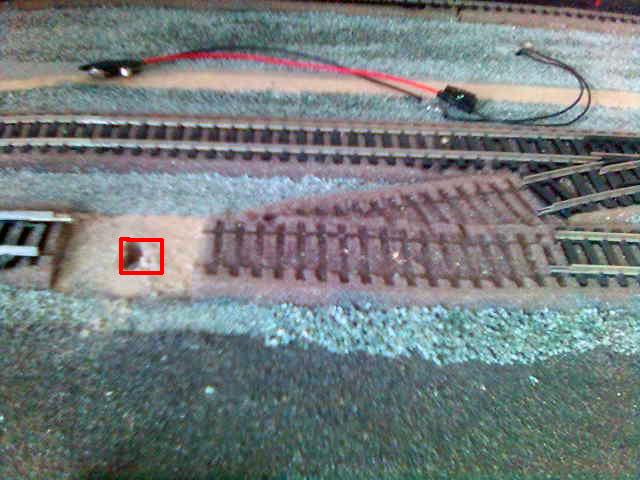
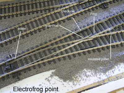
Electrofrogs Vs Insulfrogs
This is a very basic article to explain the
difference between electrofrog and insulfrog points and why you would choose
one or the other.
Below is a picture of an insulfrog point.

[click here for large image]
On insulfrog points the frog, (the V where
the two diverging rails meet) is made of plastic. Each blade is wired
to its frog rail from underneath to carry electricity across the gap. This allows for simpler wiring of the layout. The point can act as a
switch to isolate the siding when it isn't switched in that direction. The
trouble is that there is now a gap of dead track on this point. Locomotives
with only four wheels or not many pickups are quite likely to come to a
sudden stop here if their wheels aren't perfectly clean or if all the wheels
aren't firmly on the track.
All Hornby and Peco ST set track points have
insulated frogs. Peco Streamline points are available as either Insulfrog or Electrofrog.
Below
is a picture of a live frog point
[click here for large image]
On Electrofrog points the two frog rails are
metal all the way to the point. This means that the locomotives wheels can
pass over the frog without losing electrical contact but now we have a new
problem. If the point is part of a loop or if there is a power feed on
either of the tracks leading away from the frog, the frog will short the
rails together. To avoid this we have to isolate power feeds from the frog
with insulating joiners.
If one of the tracks is a siding with no
power feed of its own we can use a normal joiner and the point will switch
power to the siding the same as an Insulfrog point.
So what are the advantages of using Electrofrog points?
-
They look better, because the frog is all metal just like the real thing (although the check rails aren’t)
-
They work much better, because there is no dead section of track for the trains to stall on.
-
Live frog points are recommended (but not essential) for DCC.
What are the disadvantages of using Electrofrog points?
-
They cost slightly more
-
You need some insulated joiners
-
For Electrofrog single or double slips,
you also need switches to change the polarity of the frogs.
-
For DCC it is also recommended
(but also not essential) that Peco
Electrofrog points be modified and switches used to change the frog polarity.
[back to the top]
How does DCC (Digital Command Control) change your track design?
DCC control has almost done away with the need for isolation
sections. With DCC you can have a single siding full of locos and only the
one you want to move will.
In the past to run more than one train
you needed a second controller and a second loop of track. If you wanted to
cross from one loop to the other it involved moving the first train in to an
area where it could be isolated for example in a siding before you could
move the second train on the first trains loop. If you then wanted to move
the first train on to the second trains loop you would have to put the
second train in an isolated section and then move the first train out and on
to the second loop.
Confused? I know I am
Remembering which switches to move to do
this and having enough isolated sections of track big enough to hold both of
you trains on one loop of track is very unlikely unless you previously
thought of this.
With DCC you don’t have to worry about
this. You also wont get the problem of crossing the circuits by changing the
points, or accidentally running two trains at the same time because you
didn’t isolate one or you switched the wrong point.
The only problem with DCC is leaning how to use it and the
fact that it is very possible to run two train’s head on in to each other.
But then it wouldn’t be fun without an air of risk. There is also the
problem of modifying old locos to run with DCC. In some cases it would be
difficult to return the loco to normal control.
[Back
to the Top]
|


