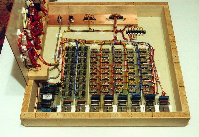
This guide will teach you how to make a control panel, like the one on my layout. Before I begin, I must add that even though it works, the way I have done it may not be the best way of doing it and there are other ways. If you have any comments or questions, feel free to say.
You will need:
Point Motors - However many you need, I used Hornby Surface mounted point motors as they are easy to fit and reasonably cheap.
Switches – Make sure they spring back to the centre, so you will need a (on)off(on) SPDT switch. Other types of switches can be used but this is my method remember! They can be obtained here: http://www.newmodellersshop.co.uk/elect ... itches.htm Again, as many as you need but remember 1 switch can control 2 points if you need it to, say if you have a crossover.
A panel to mount your switches on, explained below.
A CDU – Capacitor Discharge Unit – Can be obtained from eBay. This stops your points burning out if you keep the switch held down and also helps fire a big burst of power if you are switching more than one point.
Green, Red and Black Wire, the amount depends on the size of your layout and where your panel is in relation to the points. I have used 24/0.2 equipment wire
A power supply, mine gives an output of 16vDC, but most CDU’s will take an input of 16 to 24 volts.
A soldering iron + solder
Choc Blocks (Connector Blocks) - I used the 5A version. Again available from NRM shop.
A small slotted head screwdriver.
Wire Strippers
Soldering Iron + Solder
First of all, you are going to need a board/box to have your track plan and switches on. For this I engraved my track plan onto a piece of 4mm MDF using a laser cutter. Most people won’t have access to a laser cutter, but other alternatives are available, e.g. simple boxes, which can be bought from Maplin, or you could make your own. You could draw your track plan or use tape or print it onto card and stick it on; at this stage you can do whatever! The images below show my control panel before the sides have been taken off.


Next, you will need to drill your holes, as shown above. My switches needed 6mm holes, do a test drill outside of your plan just to check your switches fit it ok.
Your switches will then need to be screwed in, make sure you turn the underside of the switch round, so you have the switch flicking up and down or left and right or whatever you like. I liked to number my switches and points, which created an order to in which to precede e.g. Points 1 will be installed, then 2 and 3 etc. Or Switch 1 will be soldered then 2 and 3 etc.


It will start looking like a control panel now, but next comes the soldering! When I started my control panel, I was dreadful at soldering, but after a few switches I was perfect! (Well almost!) The trick for me is to make sure the iron is very hot, and then place on the connection you’re soldering for a few seconds, offer the solder to the iron close to the joint and let it flow into it.
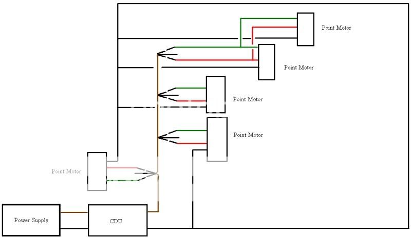
Here’s a wiring diagram that I used to help me, please note that I have more point motors and it just shows me how to do a few and that the switch at the top controls two points.
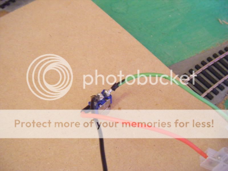
As my shed is at the bottom of my garden, I wanted to do all the soldering in my nice warm room and take it down when I was ready to attach the wires to the points, so I soldered 10cm pieces of wire to the switches in my house, so I could take it down to my shed and just connect it all up. (Alternatively you could solder the wires that will go directly to the point motor, so there is no need to do this) Solder the Green and Red wires to the outer solder lugs and solder black for the inside lug. Here’s one of my better ones when I started:


Ok, so you have soldered your first few wires or maybe all of them if you were quick. What’s next? Well you need to attach chocolate blocks to the ends of all the wires. IMPORTANT: If you are using the alternate method described above, you still need to attach choc blocks, but the ends of the black wires only, not green and red.

Next you need all the ends of the black wires to connect to the input. As it would not be possible to shove all the black wire ends into the CDU output, it is done by having a wire leading from your CDU to the choc block on the end of the wire on your first switch, a wire leading from your first switch to your second, another wire then from your second to your third, therefore you have two wires leading out of each choc block, except your last switch. (You could add your CDU now but make sure you get the first wire to be in the right output (DC-), read your CDU’s instructions and this will be shown later.) Here are some pics explaining this: Note: I hadn’t got round to soldering the green and red wires yet in these pics.


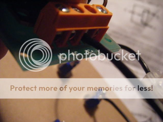
Now you have done all the soldering that you need to do, it’s time to install all your point motors if you haven’t already done so. I won’t explain how to fit a point motor as you should have instructions supplied. Hopefully, your point motor has 3 wires coming out from it: Green, Red and Black.
Once you have done all this, you are ready to connect it all up. Start with you first switch and point. Connect the red wire from your switch (or the 10cm wire with choc block) to the red wire coming from the point motor, using... You guessed it... Red wire! Repeat with the steps with Green Wire. BUT with the black wire coming from your POINT MOTOR needs to go back to the CDU, not the switch. Once again it would be silly to try and shove all the black wire into the CDU, so do a similar process to the black wires earlier. Have one wire from the CDU output (DC+)leading to two wires, one to the point and the other a short wire leading to the next two connections and so on.


You can either keep going with the rest of the wiring now or you can give your first wired up point motor a test. Before you can, take your power supply and cut of the end that doesn’t go into the wall, revealing two wires a positive and a negative. Strip half a centimetre of the plastic of each wire, and place into the CDU like shown, with the white wire on the right of the AC inputs and the other in the left AC input. As I said earlier, for the outputs: (DC-) for the wire going to the switch, and (DC+) for the wire to the point motor.


Hopefully it will work and look something like this:


If it is not working, try this:
Are your inputs and outputs of your CDU correct?
Are your connections correct and secure?
Is the power on!?
Has any of the fine wiring of the point motor snapped? (this has happened to me)
Is there a short circuit?
Does any of your soldering or bare wires on your switch touch each other?
Sometimes, my points occasionally stop, but this is usually because a wire might have been accidently tugged causing a bad connection, so undo the offending connection and redo it.
Hope you understand this and nothing has been left out. Feel free to ask any questions...
Hulldude15
Visit my layout at: http://www.newrailwaymodellers.co.uk/Fo ... 90#p367218

