
Firstly, I must give due regard and thanks to John Essex of the Heywood Model Railway Group for his article at hmrg.co.uk on electrical un-couplers for OO gauge, which provided me with the inspiration to use his idea as a basis for my revised un-coupler.
To ease photography the following images are shown on a small section of 12mm plywood and are representative of my trial.
To construct my version of an electrical un-coupler you will need the following bits and pieces.
1. A new or used Peco point motor. (makes two un-couplers)
2. A short self tapping screw (approx 15mm in length)
3. Three 30mm flat headed nails
4. Two ‘T’ shaped plastic plant labels
5. One ordinary straight plastic plant label
6. One plastic drinking straw
7. Cut off from a piece of copper strip board (40mm x 80mm)
8. 60mm length of outer sleeving from 240v mains cable (of the type used as power cable sunk into the walls of your house. Please note that 35 and 45amp cable is too thick for this project)
9. Home made washer cut from lead sheet
10 Epoxy resin
11 One push to make button
Using John’s instructions, I constructed a version using plasticard as a base and without completely dismantling the Peco point motor to save additional soldering. This version used four screws to secure it to the underneath of the baseboard but, as I have a split level layout, screwing in a confined space was impractical. I wanted a system whereby I could easily change the un-coupler should I have problems later on and, as I also required several on my layout, needed to mass produce them if possible.
MkI failed on both counts
Looking round in my shed for bits and bobs I came across the following which I thought may be useful to adapt John’s design.
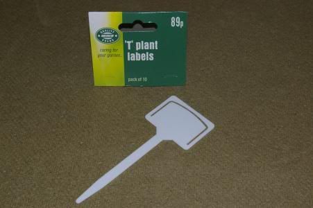
T labels (89p for 10 = 9p each)
With a little bit of cutting these proved ideal as retaining clips to hold the assembly firmly against the underside of the baseboard.
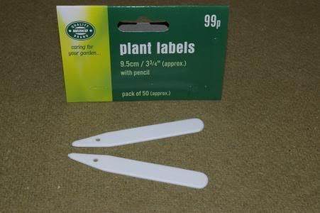
Plant labels (99p for 100 = 1p each)
Ideal for the ramp section. I found John’s lollipop stick suggestion didn’t work to my satisfaction as the panel pins worked themselves loose very quickly.

Plastic straws (50p for 6 = ? each, enough for loads of lining tubes)
To provide guide tubes for the nails. I found that my baseboard (15mm ply) left small snags when drilled preventing the guide nails dropping down which in turn left the ramp ‘up in the air’ when the power was disconnected. To prevent this, the only remedy was to drill the guide holes larger, which rendered the idea of guide pins useless as they slopped about too much or, to line the holes.
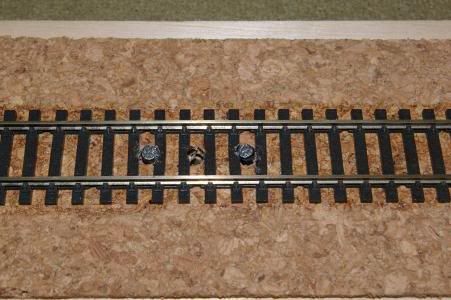
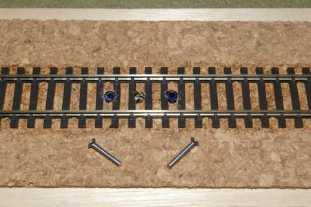
The first thing to decide is where you need your un-coupler. Select a straight section (at least 60mm long) and in the centre of this length, drill a 4mm hole in the middle of the track bed and between two sleepers. Then drill two more 4mm holes at least two sleepers either side of the first hole. This should leave you with the following – sleeper, hole, sleeper, gap, sleeper, hole, sleeper, gap, sleeper, hole, sleeper, in a straight line down the centre of the trackbed.
In the outer two holes push a suitable length of plastic straw and trim off level with the top of the sleepers and the underside of the baseboard. These should be a tight fit but glue them into position if they aren’t.
Nb. Ensure none of the straw protrudes beyond the bottom of the baseboard as this will hinder a snug fit of the un-coupler mechanism.
Drop a 30mm flat head nail down each of the outer holes making sure they can move up and down without any restrictions.
Trim off the bottom of the nails so they do not protrude beyond the bottom of the lining tubes.
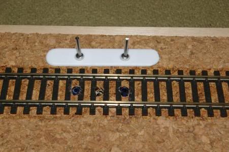
Cut a 45mm length of plastic plant label and round the cut end. This will be our un-coupling ramp.
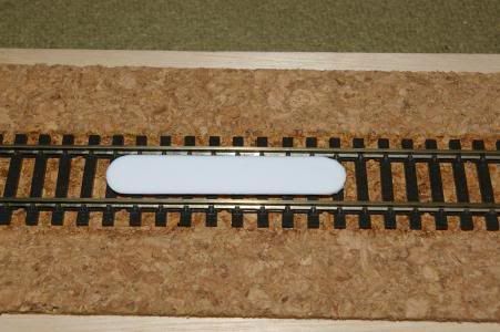
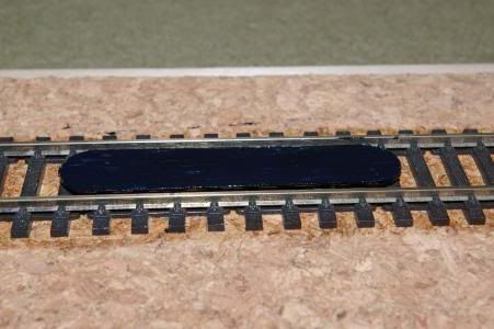
Place the shortened nails back into the two outer holes. Put a spot of epoxy glue on the top of each nail and carefully place the shaped ramp on the nails ensuring it is centered between the rails and the middle of it is over the centre hole. Leave to set and when dry, paint a suitable colour.
Nb. Be very careful with this gluing stage. If you put too much glue on it may spread resulting in your ramp sticking to the sleepers of your track.
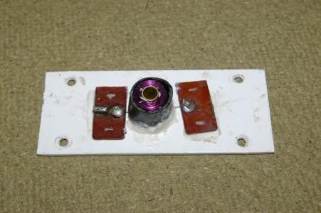
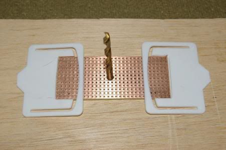
The next stage is to cut a piece of stripboard 40mm x 80mm.
Nb. I’ve tried several alternatives as a base for the un-coupler but none perform as well as stripboard. It’s expensive but undoubtedly the best for the job. I used a piece from Maplins (Part No JP21) which cost me about £5 but out of which I cut 12 bases making each one around 42p.
Drill a 4mm hole exactly in the centre of the stripboard.
Next the holding clamps. Looking at the ‘T’ shaped plant label holders there appears to be a narrow handle along two sides and across the top. This ‘handle’ will provide enough strength to hold the sub assembly firmly against the underside of the baseboard. However, to help it do its job a little better if a small rectangle (approx 15mm x 40mm) is cut from the inner plate into which the ends of the sub assembly will sit.
Using the 4mm drill bit as a centre guide, slide the stripboard onto the bottom of it and then position a retainers on one end making sure the handle goes over the stripboard. Glue the retaining clip to the underside of the baseboard ensuring the drill bit can move easily up and down the pilot hole.
Nb. Careful again when gluing this stage. Make sure none gets on the handle section and that you don’t glue the stripboard to the baseboard.
When the first end has set, position and glue the other end again making sure the drill bit moves easily up and down and you don’t glue the handle or the stripboard.
Nb. When positioning the stripboard, it is essential that two things are aligned accurately. Firstly, the centre hole must be exactly in line with the pilot hole – use the 4mm drill bit as a guide, and secondly, the stripboard must sit squarely in the retaining clip cut outs. Other than this, it does not matter which direction the base is aligned, north south east or west the only movement is up and down so you can align it to suit your needs – it doesn’t have to sit in line with the track.
We now need to motorise our un-coupler and, to do this we must obtain a Peco point motor, either new or second hand it doesn’t matter as long as it works. Assuming you buy new (about £3:50) each motor will make two un-couplers so that works out at £1:75 each. Obviously if you buy second hand it will be cheaper and, if you use an old discarded motor, even less.
Start by cutting the motor into two halves by sawing the insulated side panels with a junior hacksaw.
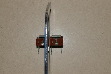
This will release the centre operating rod which can be discarded, and will leave two potential un-coupler motors.
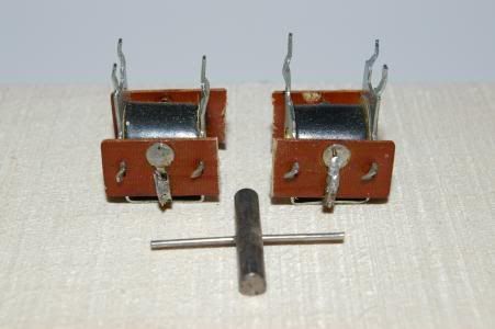
This bit requires some ‘gentle’ persuasion. If you look closely, the insulated sides are holding the assembly together by means of four tabs of metal on each side. These are twisted to provide retention and we need to gently twist these back with a pair of small pliers so they are straight again. When you’ve done this, they will simply lift away from the coil. BUT BE CAREFUL as each insulator is still attached to the coil by a piece of very, very thin wire which you must not break.
Dislodge the insulators from each side of the coil and discard the metal holding frame.
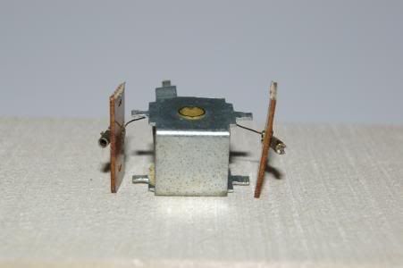
You now have to unsolder the thin wires from the insulators. I found it easier to use the 4mm drill bit as a guide in the stripboard. Slide the coil onto this allowing it to hold the coil in position. I then unsoldered each wire and immediately soldered them to a strip on the stripboard, repeating next with the other wire. You can remove the stripboard from your baseboard to carry out this part of the assembly – it’s much easier working on the bench.
At this time I also took the opportunity of soldering operating wires to the same strips as the coil wires. The only thing you have to be careful of here is that the coil wires do not end up being soldered to the same strip along the board – simple enough as you have loads to choose from. I went one long side of the board with one wire, and the second on the other long side. Obviously, each operating lead must be soldered to the same strip as the coil wire it relates to.
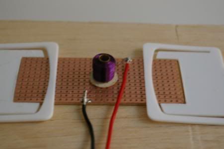
Once you’re happy with your soldering, replace the drill bit through the centre of the coil and the stripboard and epoxy the coil to the stripboard. I found it to be more effective if I removed the black outer plastic insulating cover to do this (just slide it off) and then gluing it back into place once the coil had set securely.
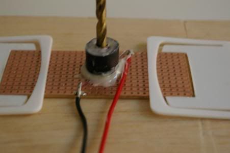
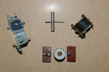
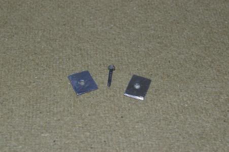
Now for the bit that moves everything up and down, the mechanism of which is very simple and straight forward, consisting of a short piece of cable insulation, another flat headed nail, a small lead washer and a small self tapping screw.
The cable insulation is stripped from the inner part of some 240v mains house type cable. (Nb 35amp and 45amp cable is too thick) you will need a 60mm approx length.
Into one end twist the self tapper a couple of turns so that it grips into the insulation firmly. Finger tight will do or you might split it.
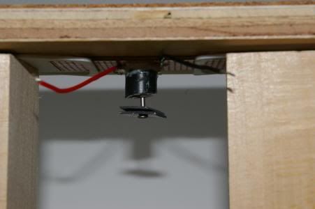
Place the stripboard assembly in position under the baseboard and drop the open end of the cable into the centre hole. (Nb it will hang well below under the baseboard.)
Trim the cable level with the end of the motor coil.
Shorten the nail to about 15mm, file the point back onto it (it makes fitting easier)
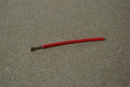
Make a small washer from a piece of scrap lead sheet. Make a hole in its centre and thread this onto the shortened nail. Finally, push this up into the open end of the cable.
The cable assembly should look something like this;-
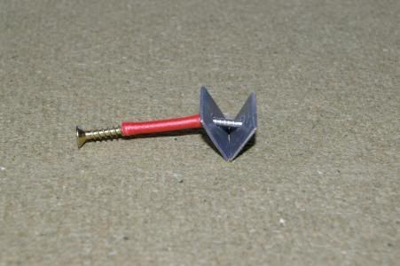
in order to position it inside the motor, remove the nail and washers, drop it in the hole and then replace the nail and washers.
The washers provide weight to ensure it ‘sits down’ after you release the power and also prevents the whole thing ejecting across your baseboard when you apply power.
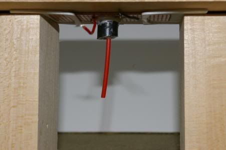
Operation. When current is applied to the two operation leads the coil energises and tries to pull the nail up into its middle tube. This in turn will lift the cable and the screw in the top end.
You may have to shorten the length of cable to obtain the desired lift height, but I find it just right as described. Don’t worry about cutting too much off as you can easily replace with another long bit and start trimming once again.
Once you have obtained the correct lift height, all that remains is to repeat an earlier stage by epoxying the ramp onto the head of the screw. Drop the scew and cable down the middle hole, dab with epoxy and then lower your assembled ramp onto the screw ensuring everything is squared up before it sets. Job done.
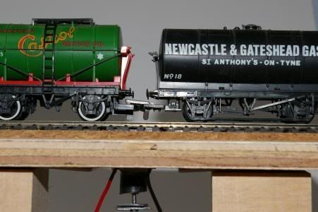
Wagons roll over the un-coupler and stop.
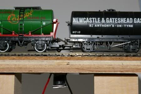
Via a push to make button apply 9 to 12v to the assembly and up she goes uncoupling the wagons. Take your finger off the button and it returns again to the ready state.
Have fun.
Mike (aka Silver Surfer)
Credits to:-
HMRG.co.uk; John Essex and the Heywood Model Railway Group for the inspiration for me to have a go.