Please give constructive criticism.
Siding detection project.
Do you have a siding on your model layout that you can't see, do your trains hit the buffers causing damage to your locomotives. Or do you want to see at a glance on your layout control panel what sidings are occupied by locomotives. Then here is the answer. A siding detection circuit.
The idea of the circuit is to detect a locomotive in a siding, either because the siding isn't in plain view or you want to see on your control panel what sidings are in use. There are several different options you can add to the basic circuit, such as an on-off feature or a location feature, this is used in longer sidings used for full length trains, more on this later.
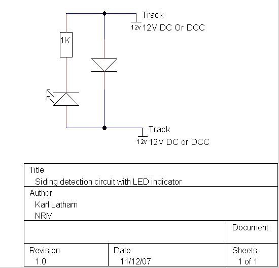
The most basic circuit is made up of three components and some 2mm wire. The component list is
1 LED
1 1K resistor
1 Diode
2mm wire
The LED should preferably be a low voltage, and not an ultra bright, trust me you don't want a control panel full of ultra bright LEDS. Now here is the circuit diagram.
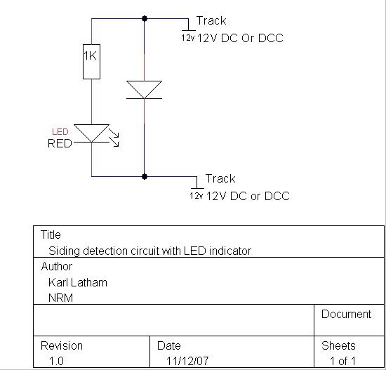
The circuit should be placed over a rail gap connected to the next piece of track with an insulated rail joiner. (Fish plate) The circuit is only needed on one side. Now there are two places to put the circuit, either place it beside the track with wires running to the LED on the control panel. The Diode and resistor are hidden under ballast. Or you can put all the components behind your control panel.
The circuit works in a very simple way, when the last set wheels on the locomotives crosses the rail gap, no more current gets to the wheels because the diode only lets power through in one direction. This illuminates the LED showing you the siding is occupied, no matter how much power you apply. When you change the locomotives direction the locomotive will move again. The LED turns off and it shows you the siding is unoccupied. A very simple beginners circuit.
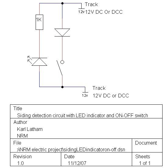
The next circuit is a siding detection circuit with an LED indicator and an ON-OFF feature. This is handy for platforms where you can automatically stop trains after the locomotive has passed a certain point and the control panel will tell you the platform us occupied.
The platform circuit is made up of the following components and some 2mm wire. The list of components is as follows.
1 LED
1 1K resistor
1 diode
1 SPST ON-OFF switch.
The LED should preferably be a low voltage, and not an ultra bright, trust me you don't want a control panel full of ultra bright LEDS. Now here is the circuit diagram.
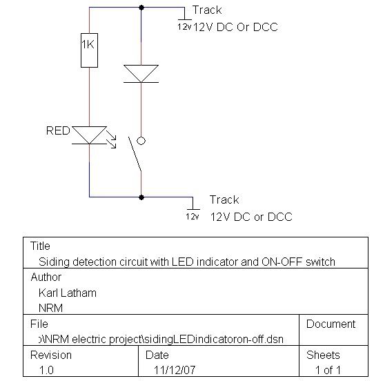
The circuit should be placed over a rail gap connected to the next piece of track with an insulated rail joiner. (Fish plate) The circuit is only needed on one side. Now the circuit can either be placed with the diode and resistor under the ballast beside the track with wires running to the switch and LED on the control panel, or behind the control panel.
The circuit works in a very simple way, when the last set wheels on the locomotives crosses the rail gap, no more current gets to the wheels because the diode only lets power through in one direction. This illuminates the LED showing you the siding is occupied, no matter how much power you apply. When you change the locomotives direction the locomotive will move again. The LED turns off and it shows you the siding is unoccupied. The switch allows you to chose to have the circuit ON or OFF handy in a station where you want passenger trains to stop and freight trains to pass through. This is also a very easy circuit for beginners.