NRM Article - An attempt - Infra-Red in OO

Articles which have been added to the main site
Silver Surfer
Posts: 153
Joined: Thu Apr 13, 2006 2:05 pm
Location: 16A

NRM Article - An attempt - Infra-Red in OO

Post by Silver Surfer »

I'd always considered going down the DCC route (I'm presently fully DC) but wanted if possible to eliminate the need to have powered track. I don't know why but I've always suffered from slow running engines stalling on points etc and it's a real pain.

In the June 2007 edition of Railway Modeller was an article on the Bodmin 0 gauge layout of Ray Green using Infra Red train control. Could this be the answer to my prayers? I began researching and a couple of days later saw me on a visit to Steve Leyland at MicroMotive in Clay Cross Derbyshire, to have a look at their IR system 'Red Arrow' http://www.a1micromotive.co.uk/Red%20Arrow%20home.html

Needless to say I returned home with an IR system - a controller and a bag of bits capable of fitting out two loco's
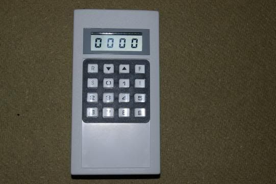
Image

THE CONTROLLER &

Image

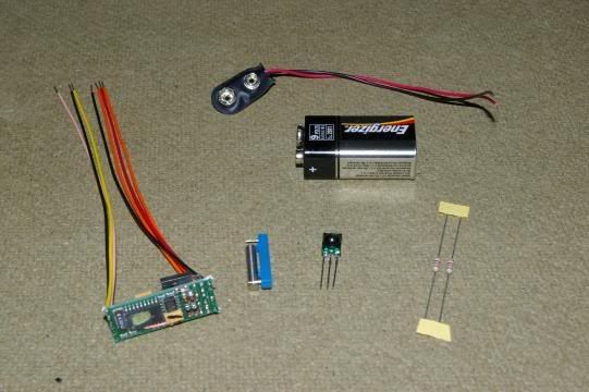
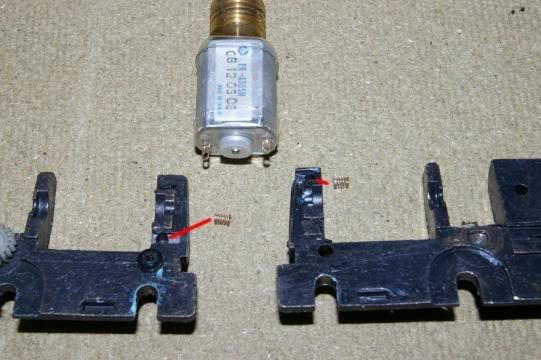
THE BITS - Which are left to right:-
The module
Reedswitch
IR detector
Limit resistors
(nb You have supply the battery and connector)

After reading the instructions several times I assembled a test rig to try out the bits before attempting to fit them in a loco.
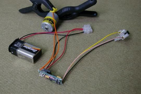
Image

TEST RIG

I only used a small 3volt motor for the test but everything worked great.

Now came the bit I really hated, butchering a loco and tender - it always seems like sacrilege to deliberately damage something you've probably treasured for years. So I called it surgery and made every effort not to to more damage than was absolutely necessary.

This pic shows the module on the back of a Bachmann Jubilee tender - just to give an impression of size.
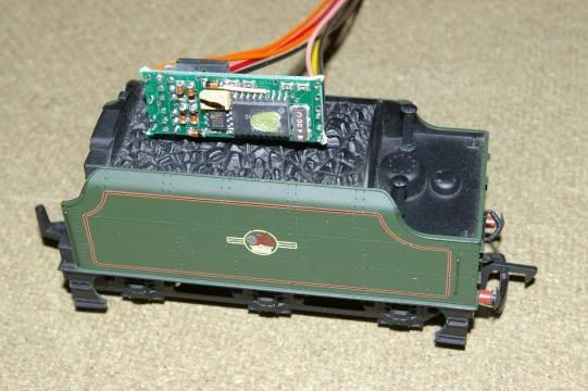
Image

MODULE ON TENDER

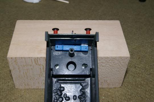
The first job I did (I realised later that this should have been left until later because if I couldn't get the module and battery in the tender then this bit would have been pointless, still - lesson learned) was to remove the power pickups from the loco, as I was fitting a new power source.

No easy ride for me then. Stripping the Jubilee, I soon realised there were no actual pickups, but this one used a split metal chassis with two springs pressing onto the motor contacts. MMmm.

Image

SPLIT CHASSIS
The two little springs fitted in the holes shown. They simply pressed against the motor contacts on the can.

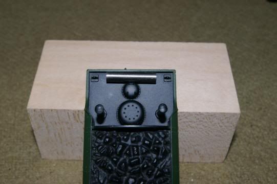
I decided to remove the springs (saving them for later), isolate the contacts and take two leads out the rear of the loco to the tender.
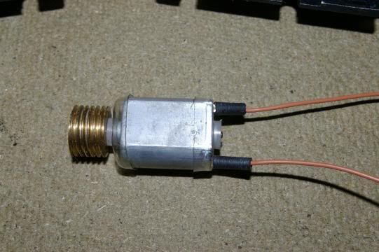
Image

ISOLATED CONTACTS.

The rubber isolators shown didn't work as they were too bulky to allow the sides of the chassis to be assembled correctly. I eventually changed them for two small pieces of insulation stripped from mains cable.

Image

MOTOR FEEDS FITTED.

I re-assembled the loco and simply hooked up a 9v battery to the two leads. First thing I noticed (this was a new standard PP3 battery) was an apparent loss of power and the engine didn't seem to go as fast as before. I stripped it down and re-assembled it again - same result, so I placed the loco on track and bingo it went as fast as before, so it must be the fact it is powered by 9v instead of 12v.
This may be a problem when it hauls decent length trains but, as still had plenty to do, would have to be tested later.

Now the butchery, sorry surgery, on the tender.

Inside the tender of the loco are three metal plates used as ballast. My first go was to remove the middle one and replace it with a suitably trimmed piece of plasticard which I split across the middle, put them back in, creating a slot through which I could thread a cable tie to secure everything piggy back style.
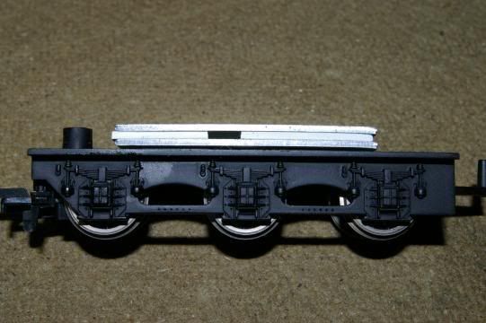
Image

CABLE TIE SLOT.

I stacked the battery and module onto the plates. A bit like this:-

Image

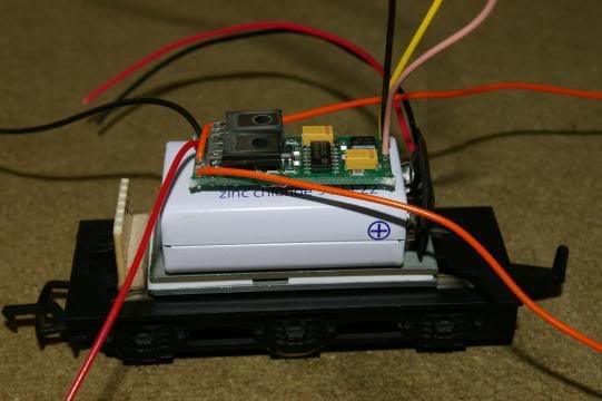
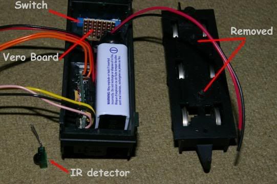
PIGGY BACK (nb the little thing sticking up at the coupling end is veroboard - see later)

In addition to these bits, I still had to fit the detector, a reed switch, a limit resistor, a bridge rectifier plus connections etc - would I have room?

The switch was no problem. The one supplied is a proximity reed switch supplied with a magnet. In its normal state the contacts are closed - allowing a circuit. Put the magnet onto it and the contacts break thus breaking the circuit. A little test showed the magnet was powerful enough to work through the tender sides.

Image

REED SWITCH
Using double sided tape the switch was stuck to the underside rear of the tender.

Image
All I have to do to turn off the power is to rest the magnet on top of the tender as shown above.

I then had to manufacture an assembly containing a bridge rectifier and a limit resistor (which I think is 720ohm_. This is not absolutely neccessary but means dismantling the tender each time the battery goes flat. What I wanted was to be able to charge the battery by standing the loco on live track.

So a short while later I had made this bit of kit (on the veroboard shown above) and fitted all the parts onto the tender chassis and tried to put the top on................Absolutely no way would they all go in.

Think and re-think and re-re-think.

I then remembered a classic bit of advice my old Dad gave me when I was repairing a motorbike or something:-
"If thy canna fit it reet, turn t'arse about face 'n try agin"

Interpretation - If you can't get something to fit correctly, turn it upside down and try again.

Exactly Dad, thanks. I was trying to put everything on the chassis and hoping the top would fit. I took everything off and placed it in the now upside down body shell, which seemed much easier really.

Trying it again I was till struggling for space, so out came the ballast plates and their securing supports - just about do it if I place the detector in the top but on one side of centre.

Image

PACKED IN THE TENDER SHELL.

This view shows the detector epoxied into the roof of the tender but placed to one side to allow maximum room for the battery.
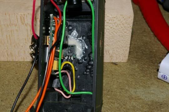
Image

INTERNAL VIEW

and another view from the topside - I have still to tidy this up as the epoxy seeped through the gap a little.
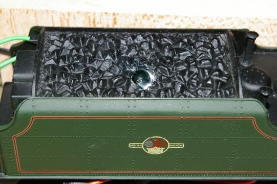
Image

TOPSIDE.

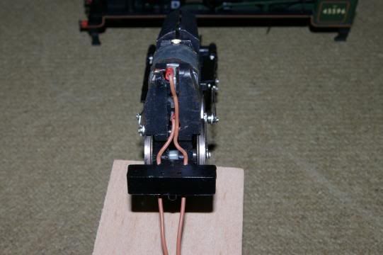
HURRAH. Everything fitted - but would it work?
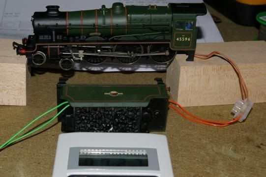
Image

WORKING TEST

This shot shows the engine, yet to be connected properly to the tender, under test. WORKED FIRST TIME. The wheels are actually turning quickly but the camera has frozen the action.
(nb. Ignore the green wires which will eventually be used as power pickups for the battery re-charge system).

One or two problems but I got there. I'm quite satisfied actually as, other than wiring up a few LED circuits,I've absolutely no experience or knowledge of electronics.

Problems detected and yet to be resolved:-
1) Apparent lack of power (9v versus 12v) will it pull a train?.
2) The system allows programming of 99 locos. Factory default sets all chips at 27 but I can't re-programme this one. It won't move off 27.
3) Reading the instructions I think I need a transistor heatsink. I've a rough idea of what it is and what it does but, how big is it, where do I fit it and where do I get it from.
4) Still to fit power pickups for battery re-charging. Should this be via tender wheels (easier) or should I strap them on the loco split chassis (better pickup)?
5) The jubilee has a moulded coal load forming the roof of the shell. What to do about those that have little or no coal?
6) Will the continual charge/discharge ruin the battery.
7) Once finally connected, the engine and tender are paired for life with the wires going from one to the other. Can I find a miniature or micro connector small enough to do the job?

Some things I have learned;-
It won't fit in tank engnes.
It won't fit in locos with tender drive motors.


Well that's as far as I've gone so far. I'll keep you updated of my progress.

Mike
mumbles
Posts: 1802
Joined: Sun Nov 12, 2006 11:23 pm
Location: Kent
Contact:

Post by mumbles »

hi
nice article. looks like a lot of fiddly work but i'm sure it will be worth it, to see the trains running very slowly over points [cough.. video]
:D
thanks for taking the time to do it
michael
ELR
Posts: 15
Joined: Tue Aug 29, 2006 10:47 pm
Location: Lancashire

Post by ELR »

Nice article Mike.

I think your concern about the battery is valid.
NiCad batteries last longer if given a full discharge on a regular basis. Also if they are only part used then recharged repeatedly there life is shortened. Just have sections of track as in an MPD for charging. Individually switch these sections so that some engines can be charging while fully charged engines are turned off.
Silver Surfer
Posts: 153
Joined: Thu Apr 13, 2006 2:05 pm
Location: 16A

Post by Silver Surfer »

Just an update on a few problems initially identified:-

Problems detected and yet to be resolved:-

1) Apparent lack of power (9v versus 12v) will it pull a train?.
It will pull a five coach train with ease although the max power has been reduced. Not a problem for me as I prefer realistic train speeds.

2) The system allows programming of 99 locos. Factory default sets all chips at 27 but I can't re-programme this one. It won't move off 27.
Now sorted. User error.

3) Reading the instructions I think I need a transistor heatsink. I've a rough idea of what it is and what it does but, how big is it, where do I fit it and where do I get it from.
Not yet completed.

4) Still to fit power pickups for battery re-charging. Should this be via tender wheels (easier) or should I strap them on the loco split chassis (better pickup)?
Not yet completed.

5) The jubilee has a moulded coal load forming the roof of the shell. What to do about those that have little or no coal?
I'm doctoring my second engine at this time (a Dapol County Class which has little coal in the tender) requires serious surgery and the installation of a false coal load.

6) Will the continual charge/discharge ruin the battery.
Not according to Micro-motive provided the supplied limit resistors are fitted.
(nb.The limit resistors supplied are 120ohms and not 720ohms as stated above in my article)
I've fitted some 9v 300mAh NIMH re-chargeables from Maplins - pricey at £9.99 each but up to the job. Had five coach train running 3 hours at max speed without any noticeable fall in speed or power.


7) Once finally connected, the engine and tender are paired for life with the wires going from one to the other. Can I find a miniature or micro connector small enough to do the job?
Yes found one (thanks to Micro-motive) and fitted. Nice miniature bit of kit.

Will keep you posted

Mike
ELR
Posts: 15
Joined: Tue Aug 29, 2006 10:47 pm
Location: Lancashire

Post by ELR »

Sounds like its going well
9v 300mAh NIMH re-chargeables
NIMH batteries don't suffer the same as NiCAD's but as you found are more expensive
Gordon H
Posts: 214
Joined: Tue Mar 14, 2006 1:08 pm
Location: UK
Contact:

Post by Gordon H »

Silver Surfer wrote: 6) Will the continual charge/discharge ruin the battery.
Not according to Micro-motive provided the supplied limit resistors are fitted.
(nb.The limit resistors supplied are 120ohms and not 720ohms as stated above in my article)
I've fitted some 9v 300mAh NIMH re-chargeables from Maplins - pricey at £9.99 each but up to the job. Had five coach train running 3 hours at max speed without any noticeable fall in speed or power.
Is this on level track only, or are any gradients involved?
What was the motor being used (i.e. what type of loco) ?
Just interested to understand how much current is being drawn in these circumstances to see if the figures make sense from an electronics point of view.
7) Once finally connected, the engine and tender are paired for life with the wires going from one to the other. Can I find a miniature or micro connector small enough to do the job?
Yes found one (thanks to Micro-motive) and fitted. Nice miniature bit of kit.
Any information on these? Are they a standard type of manufactured connector that they have adopted?
The Great Bear
Posts: 23
Joined: Fri Dec 01, 2006 12:48 pm
Location: SouthWest

Post by The Great Bear »

Nice job Mike and thanks for posting. Did you buy the standard or advanced kit and how is the line of sight working? I.e. do you loose control at all. This would be a great way of running another loco on the same track as a dc loco - I'm interested. I wonder whether the electronics could take 12V? There's loads of rechargeable battery options you could use other than the rechargeable PP3 to get slightly different voltages and possibly suite different spaces and give a higher top speed if this was an issue. One word of warning - if the manufacturer says the transistors need a heatsink, don't burn them out before you fit one! I would have thought the manufacturer would give guidance on this matter. If not, you may find specific heatsinks for those transistors. Else a piece of aluminium attached with some heat transfer compound would do. Finally, can you PM me details of the micro-connector please! I did a quick search under that name but nothing came up.
Regards Tim (GB).
Paddy D
Posts: 166
Joined: Fri Dec 30, 2005 8:38 pm
Location: ireland

Post by Paddy D »

that is idea ive tought about but there it is and it is great
you can buy a 16m range radio transmitter and recevier for €16 in maplins so you dont have to point it everywhere
Silver Surfer
Posts: 153
Joined: Thu Apr 13, 2006 2:05 pm
Location: 16A

Post by Silver Surfer »

Hi Tim (to try and answer some of your questions)

Standard kit. They do apparently produce a smaller chip - smaller in width not length.

The detector which has a flat bottom and a domed top will work no matter which way up it is facing but there does appear to be an issue with the reception horizontally as it seems to have a blind spot across the centre somehow. I find I spend a lot of time with my arm in the air making sure the transmitter is pointing down which is not a problem on the top level of my layout but on the lower level is. I've not yet had time to rig some reflective surfaces to overcome this. If it remains a problem I may consider some form of radio transmission as Paddy suggests.

Re running on 12v. I posed this question to MicroMotive as I have two locos (a tank engine and a black five with tender drive) in which I doubt I can fit the battery and chip. I was told I could connect the battery leads directly to the track supply via a 120 ohm limit resistor and it would then run okay, although I haven't tried it yet.

Be interested to hear your suggestions re the batteries as the PP3 is a real pain in the preverbial - needs lots of room, but does keep the motors running under load for a long time.

The manufacturer has given me advice on fitting heatsinks and is very much as you suggest.

I'm still awaiting the details of the micro-connector.

I'm happy with the Bachy Jube I've done (I've not yet connected the battery re-charging pickups) and have started on a Dapol GWR County. This requires major surgery as the tender has greater detailing and little if any coal in it, really testing my ingenuity.

Her in doors has me doing some major landscaping in the garden at present so having to spend time away from the layout - doing a lot of thinking though.

If you want to speak to micro motive give them a call and ask for Steve Leyland - he's a real nice guy and very approachable. They have a web site at www.a1micromotive.co.uk just click on Red Arrow on the front page.

Mike
RAF
Posts: 74
Joined: Sun Feb 11, 2007 9:40 pm

Post by RAF »

Isn't it great when you think of a great idea and then DAMN, someone already did it first...

http://www.newrailwaymodellers.co.uk/Fo ... php?t=6278
Kindling
Posts: 120
Joined: Sun Jul 01, 2007 2:36 pm
Location: Derbyshire

Post by Kindling »

I would just like to ask Silver Surfer how things are going with the infra-red system. I hope all is well.
edwardholmes91
Posts: 374
Joined: Tue Jul 10, 2007 10:57 pm
Location: Stone, Staffordhshire, England
Contact:

Post by edwardholmes91 »

As for the batteries, electronics is constantly developing and technology is getting smaller and smaller, so you must be able to get batteries quite small. I have also come up with the idea of using capacitors maybe, as they are not damaged by constant charging and recharging. Hookedup to a voltage regulator and hey presto, no battery needed! :)
Kindling
Posts: 120
Joined: Sun Jul 01, 2007 2:36 pm
Location: Derbyshire

Post by Kindling »

Sorry to nag, but please, Silver Surfer, tell us how things are working out with this system.
Thanking you in eager anticipation!
Silver Surfer
Posts: 153
Joined: Thu Apr 13, 2006 2:05 pm
Location: 16A

Post by Silver Surfer »

Hi Kindling and others who have shown interest in the infrared system. Sorry I've not answered but been rather busy and not checked my web articles pages. May have been an idea to send a PM asking me to update.

How is it going? well, put simply, it's in the bin. I've saved the bits as I'm thinking of possibly using it to control my Traverser, but not my trains.
The system is good. I had no great problem eventually fitting the mechanics into the tenders and slow running was superb but my problem was with 'line of sight' from the controller to the receiver fitted in the tender(s). The receiver is dome shaped and was fixed into the tender coal loads but after a great deal of trouble getting the thing to accept instructions, I discovered the receivers had a blind spot and any beam aimed at it lower than 45 degrees (that's 45 degrees upwards from the horizontal) was not accepted. Therefore this meant I either had to stand up and point it downwards at the tender or sit with my arm in the air pointing the controller downwards which as you can imagine gets a bit irksome after a while. My lower level was an absolute no go area with infra red as I couldn't get it to receive at all and many multiple pile ups ensued.

Probably with different receivers it would work satisfactorily but quite honestly, having spent what seems like zillions of hours getting nowhere, I decided to remove the decoders and revert to bog standard DC.

If anything the experience has made my mind up about one thing - I won't be going down the DCC route. I'm a hands on type and I like my trains to respond to rotating knobs or pulling levers etc and I have enough of keyboards with my computer.
DCC is the current buzz word and the 'thing to have' as far as manufacturers are concerned, well they would wouldn't they, you only have to look at the millions of pounds they make producing it. However, I don't think pressing keys on any type of keyboard is the way to drive trains, an argument that I could justify given that it doesn't happen that way in the real world so why should it happen on my model railway?

Don't get me wrong, I'm all for an 'each to his own' way of going on and, if you like DCC that's great by me, I won't argue with you either for or against. I just don't think its the be all and end all of railway modelling that manufacturers would have us believe, and that's just my opinion. Infra red is a sort of half way house between DC and DCC but costing much much less than DCC and I'm glad I gave it a go, maybe with further development it could be a winner but it's not for me. I'm now happy to stay with DC, have eliminated the DCC option, and can get on with something akin to feeling as though I'm driving a train.

Mike
Kindling
Posts: 120
Joined: Sun Jul 01, 2007 2:36 pm
Location: Derbyshire

Infra Red

Post by Kindling »

Many thanks for that, Silver Surfer. Yes, now I know what "P.M ing" is, you are right, I should have done it. However, please understand I'm knocking on a bit and am highly computer illiterate (and that is not a typing error!).

I will still consider the infra-red system as I like its good aspects. I take on board your practical points and will see if there is a way round it. (I am considering it for O-gauge).

Strange as it may seem, I entirely agree with your point about knobs and levers. Having to repeatedly "toggle" buttons is one aspect that is putting me off!
Post Reply