Modular DCC Inglenook

Post your design ideas for any layout that you are planning to build in the future. Keep members up-to-date with your designs and future plans for your layout.
User avatar
minipix
Posts: 142
Joined: Fri Nov 03, 2017 1:29 pm

Modular DCC Inglenook

Post by minipix »

Exciting news, I've decided to begin a new project! The aim, ultimately, is to have a small, modular Inglenook-style shunting layout, with point motors and DCC, on a minimal budget. This isn't intended to be particularly scenic, but will serve as a technical experiment to try out new techniques and make sure I can do things properly on a small scale before ramping up to a larger layout (maybe one day).

What I already have:

* Some wood (chipboard (I think) from an old chest of drawers)
* Some flexi-track (Peco code 100)
* Two medium-radius Peco electrofrog points
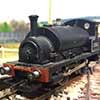
* A Hornby Terrier 0-6-0
* Some wire
* Glue, nails, bolts, tools, etc.

Basically, this is all leftovers. But if I had to buy it outright, it wouldn't cost the earth.

Phase 1 will be getting the boards built, the track wired, and point motors installed. Initially, for reasons of cost (and spreading out the work) this will be using DC control. I'll have three boards, which will be 430x230mm each, braced underneath and connected together with some bolts; essentially there will be one board with a headshunt, one with the points, and one with the sidings. I'll be using Gaugemaster PM1 seep points (with polarity switch), which I'll wire up to a CDU and some switches to operate the points and feed the frogs. I'll make my own controller using a cheap PWM module. Here's what I anticipate needing to buy:

* 2x PM1 seep point motors
* CDU
* PWM controller with direction switch
* 2x momentary SPDT switches
* 12V DC power supply (for motive power)
* 12V AC power supply (for point motors)

If all goes according to plan, I'm expecting a total outlay of around £30 to cover this entire phase of the build. I'll end up with a DC controlled Inglenook that I can pack into a small crate.
Annotation 2019-11-22 125908.jpg
Phase 2 will be about converting the layout to DCC, having wired the layout originally with DCC in mind. I'm planning on going down the DCC++ route, mainly for budget reasons. I'll use a free mobile phone app, connecting via Bluetooth to a Raspberry Pi running JMRI, which will communicate via USB to an Arduino with a motor shield, which will in turn be connected to the power bus installed in phase 1. I'll probably buy a cheap screen for the Raspberry Pi so I can check everything is working and do the loco programming, but once it's set up it should just boot up on its own. I'll attempt to install a small DCC decoder inside the Terrier (advice gladly received here!). Here's what I anticipate needing to buy:

* Raspberry Pi
* Arduino Uno
* Motor shield
* DCC decoder (Lais? Hornby?)
* Computer monitor

This is slightly more expensive than phase 1, but I'm guessing a budget of £50 should be about right, if I find some good bargains.

Does anything look wrong to you? Is anything noticeably missing? Have I got the power supply requirements right?
Frontington & Backwoods Railway: https://www.matthewdawkins.co.uk/catego ... way-build/
LocoSound - sound effects for DC model railways: https://mafu-d.github.io/loco-sound
User avatar
minipix
Posts: 142
Joined: Fri Nov 03, 2017 1:29 pm

Re: Modular DCC Inglenook

Post by minipix »

Well, progress has been made already, which is exciting. Last night I did a big clear-up in the garage to rediscover my workbench, which will also serve as a home for this new layout. A piece of wood was then cut up and some points offered up in a rough position.
IMG_20191122_212709274.jpg
It turns out the points fit exactly on the 430mm width of wood, which is convenient. The tricky bit will be joining the piece of wood together reliably such that the pieces of track line up - that could take some fettling. Does anyone have any advice here?

With the points in a good place, I drew around them in pencil and marked where the holes will need to go for dropper wires and suchlike. Then the holes themselves were drilled. There were already some holes in the wood from when it was a chest of drawers, so I've labelled everything to make sure I don't get confused! I'll also need to drill a couple more holes when I've sorted out where the dropper wires will go for the straight. Connections from the droppers to the bus will be done via choc blocks. And since the boards are designed to come apart, I'll need a quick and easy way to plug the bus together - WIP.
IMG_20191122_220042337.jpg
I've marked on the underside roughly where things are going to live, such as the bus wires and point motors. Once I've got the CDU I'll find somewhere suitable to mount that too.

Speaking of which, I've now placed a couple of orders for my new parts. The two point motors, CDU, PWM controller and various switches all came to almost exactly £25, so all I need to find now is power supplies. What would you recommend for powering a couple of seep point motors? Can I use an old laptop power supply?
Frontington & Backwoods Railway: https://www.matthewdawkins.co.uk/catego ... way-build/
LocoSound - sound effects for DC model railways: https://mafu-d.github.io/loco-sound
Paul-H
Posts: 244
Joined: Fri Jun 05, 2009 3:00 pm

Re: Modular DCC Inglenook

Post by Paul-H »

For reliable board alignment have a look at using board alignment dowles, available from most good suppliers
User avatar
Bufferstop
Posts: 13821
Joined: Thu Mar 11, 2010 12:06 pm
Location: Bottom end of N. Warks line

Re: Modular DCC Inglenook

Post by Bufferstop »

Consider using mechanical/hand point operation in phase 1, and using the new Peco point motors in phase 2. They are designed to allow retrofitting from below.
Growing old, can't avoid it. Growing up, forget it!
My Layout, My Workbench Blog and My Opinions
User avatar
minipix
Posts: 142
Joined: Fri Nov 03, 2017 1:29 pm

Re: Modular DCC Inglenook

Post by minipix »

@Paul-H, dowels is a good idea. As it happens, I'm pretty sure I have some knocking around, left over from various items of furniture that have since been taken apart. If I understand correctly, the idea would be to drill holes in the sides of the board, and push a dowel into one end so that the board always reconnects in the same place. I'm guessing the hard part is getting the holes to line up perfectly to begin with - any tips?

@Bufferstop, actually installing the point motors is one of the things I'm looking forward to, as it's something I've never done before. This project is basically an opportunity for me to learn how to do point motors and DCC on a small and manageable layout.
Frontington & Backwoods Railway: https://www.matthewdawkins.co.uk/catego ... way-build/
LocoSound - sound effects for DC model railways: https://mafu-d.github.io/loco-sound
User avatar
luckymucklebackit
Posts: 3712
Joined: Mon Jul 18, 2011 7:05 am
Location: Eaglesham (Again)
Contact:

Re: Modular DCC Inglenook

Post by luckymucklebackit »

minipix wrote:@Paul-H, dowels is a good idea. As it happens, I'm pretty sure I have some knocking around, left over from various items of furniture that have since been taken apart. If I understand correctly, the idea would be to drill holes in the sides of the board, and push a dowel into one end so that the board always reconnects in the same place. I'm guessing the hard part is getting the holes to line up perfectly to begin with - any tips?

@Bufferstop, actually installing the point motors is one of the things I'm looking forward to, as it's something I've never done before. This project is basically an opportunity for me to learn how to do point motors and DCC on a small and manageable layout.
Careful there - I am sure that the type of dowels Paul-H is referring to is the ones specifically designed for layouts (such as these)https://www.ebay.co.uk/itm/222534535660. Having buit many flat pack pieces of furnature I also know the wooden dowels that you are talking about, now I appreciate that you are going for a low budget but the wooden ones will work loose very quickly and will then be inneffective. Sometimes it is worthwhile spending that bit extra to get the desired result.

Jim
This Signature Left Intentionally Blank, but since I have written this and I intended to do it, this Signature is intentionally not blank. Paradox or What?
My layout - Gateside and Northbridge
Image
Paul-H
Posts: 244
Joined: Fri Jun 05, 2009 3:00 pm

Re: Modular DCC Inglenook

Post by Paul-H »

Not wooden dowels

This is the type I use

https://rover.ebay.com/rover/0/0/0?mpre ... 0743290768
Giraffe
Posts: 56
Joined: Fri May 16, 2008 1:31 pm

Re: Modular DCC Inglenook

Post by Giraffe »

minipix wrote:Phase 2 will be about converting the layout to DCC, having wired the layout originally with DCC in mind. I'm planning on going down the DCC++ route, mainly for budget reasons. I'll use a free mobile phone app, connecting via Bluetooth to a Raspberry Pi running JMRI, which will communicate via USB to an Arduino with a motor shield, which will in turn be connected to the power bus installed in phase 1. I'll probably buy a cheap screen for the Raspberry Pi so I can check everything is working and do the loco programming, but once it's set up it should just boot up on its own. I'll attempt to install a small DCC decoder inside the Terrier (advice gladly received here!). Here's what I anticipate needing to buy:

* Raspberry Pi
* Arduino Uno
* Motor shield
* DCC decoder (Lais? Hornby?)
* Computer monitor

This is slightly more expensive than phase 1, but I'm guessing a budget of £50 should be about right, if I find some good bargains.

Does anything look wrong to you? Is anything noticeably missing? Have I got the power supply requirements right?
I have built the DCC++ setup as you describe above. I am planning to attempt to rebuild using a plain ATMega chip in place of the Arduino and a motor driver board in place of the Motor Shield, which drastically reduces the price of those components (although you would need a chip programmer if you don't have one - although if you have an arduino knocking around I understand you can use that as a programmer). I haven't yet tried whether this actually works or not.

For the Raspberry Pi, I used an old B+, and it was fairly slow to boot up and load JMRI. I haven't got around to figuring if there is a way to run JMRI headless without X, but I was also planning to write a simple server that was designed for simple installations that spoke WiThrottle and DCC++ commands, designed to run on something as small as the ZeroW.

For my experiences of converting locos to DCC, check out my workbench thread: viewtopic.php?f=49&t=53583

Good luck!
User avatar
minipix
Posts: 142
Joined: Fri Nov 03, 2017 1:29 pm

Re: Modular DCC Inglenook

Post by minipix »

Thanks for all the feedback folks!

I do understand the point about dowels, but I think the size and purpose of my layout is not really sufficient for anything so bullet-proof as the metal ones you linked to. They do look wonderful, and if I had a larger layout I anticipated taking to shows then I'd definitely consider it. But for my little project it seems like overkill, so I'm sticking with the wooden dowels for now. But feel free to say "I told you so" in a few months' time when it all goes pear-shaped!

@Giraffe, thanks for your thoughts. It's good to know there are other options out there too. I'll definitely check out your workbench thread - you can never do too much research! For my part, I'm looking at getting a Raspberry Pi 3 W. No idea on boot times, I'll know when I get it, but the intention (if I follow the instructions properly) is that it will run headless. That said, I'll probably need a screen to begin with so I can program my locos.

I did manage to work on the layout briefly last week. I've drilled holes for the wooden dowels and installed those, and the boards line up very nicely. I then turned my attention to one of the points, and began the scary task of wiring it up. I say scary because my previous experience was using insulfrog points on a DC layout, with the point blades directing the polarity; on this layout I'm using PM1 seep point motors with integrated polarity switch, so I had modify the point accordingly. It's not a brand new point (probably 20 years old), so the sleeper arrangement wasn't exactly as I had seen in photos, and it turned out that I couldn't solder my wires directly to the underside of the track, and instead had to attach the wires to the sides of the rails. I'm not sure it's the best solution, maybe I'll take a different approach with the other point. But in any case, it's wired, and I've tested all the connections with a circuit tester, and I've test-installed it on the board.

The next step I think will be doing the same wiring on the other point, hopefully better. Then it'll be on to installing the point motor, CDU and switches. Hopefully, with all that done, I'll have two working points with automatic frog polarity switching! I still won't have any power to the tracks, mind you, so I won't be running any trains any time soon, but hopefully the patience will bear fruit eventually!

You'll also notice from the photos that I haven't used any cork. I'm not worried about sound deadening, and I'm not too fussed about getting a ballast shoulder either, so I'm thinking I won't need any. What I might need to do though is thoroughly sand the surface, as it's quite shiny at the moment and getting anything to stick to it (like glue or paint) might be a challenge. Thinking about it, I should probably do that before I permanently install the points...
Attachments
IMG_20191208_221144765.jpg
IMG_20191208_201557029.jpg
Frontington & Backwoods Railway: https://www.matthewdawkins.co.uk/catego ... way-build/
LocoSound - sound effects for DC model railways: https://mafu-d.github.io/loco-sound
Dad-1
Posts: 7327
Joined: Sun Aug 24, 2008 8:05 pm
Location: Dorset - A mile from West Bay.

Re: Modular DCC Inglenook

Post by Dad-1 »

I couldn't read the overall length, but for such a layout can't you get it on one board ?
HS2, or HSII whichever I feel like using is 48" long and travels in one piece.
You may find a look at viewtopic.php?f=22&t=50741&start=75#p633830
worth the time. Particularly the hand operation of points via parked road vehicles.

Geoff T.
User avatar
minipix
Posts: 142
Joined: Fri Nov 03, 2017 1:29 pm

Re: Modular DCC Inglenook

Post by minipix »

Geoff, the layout is made of three boards, each 430x230mm, which means a total combined length of 1290mm, or a little over 50". I probably could fit that all onto one board, if I had a nice big car to transport it in. To be honest, this project is more about seeing what can be done on a budget, so rather than buying a brand new piece of wood I used what I had to hand, which was an old little chest of drawers. And having three small boards means I can stack them on top of each other in a crate, which ought to fit nicely in the minuscule boot of my Mini.

More progress has been made, by the way. I was working on the central board again last night. My first attempt at soldering the wires to one of the points was a bit of a mess, as I couldn't solder directly the underside of the rail because the plastic sleepers were in the way, so I soldered to the sides of the rails instead. When I came back to it last night I decided to undo all of that, cut away the plastic webbing in a few places and do it properly. I did both points that way in the end, and they're both so much neater. Of course, I did have to drill new holes in the board, because the wires are now in slightly different places.
IMG_20191221_213721293.jpg
I also aligned and installed the PM1 point motors, and added in the beginnings of a DCC power bus. As it happens I've been clearing out some old cables, but put aside an old kettle lead; I stripped the outer sleeve to reclaim the three wires inside, and I've used a couple of those for my DCC bus wires. It would have been better with red and black, but I'm making do with what I've got! You'll also just about see in the picture some bullet connectors at each end so I can connect the other two boards; again, there is almost certainly a better way of doing that, but I happened to have these knocking around in the garage already, which effectively makes it free.

The next step will be installing the capacitor discharge unit and wiring that up to the point motors and some switches. I'm very slowly creeping towards the point of being able to actually run a loco! I also now have even more respect for people with large layouts who have to go through the same steps as me but on a much larger scale.
Frontington & Backwoods Railway: https://www.matthewdawkins.co.uk/catego ... way-build/
LocoSound - sound effects for DC model railways: https://mafu-d.github.io/loco-sound
User avatar
minipix
Posts: 142
Joined: Fri Nov 03, 2017 1:29 pm

Re: Modular DCC Inglenook

Post by minipix »

Time for another update.

The wiring for the points is now more or less complete, having installed the CDU and two momentary switches, and soldered everything up. It's looking a little more busy on the underside now! The only remaining thing now is to source a suitable power supply. I thought I had an old laptop charger knocking around, but I can't find it at the moment. I tested it with a smaller power supply (12V DC I think it was), which confirmed that the PM1s should be wired up correctly - flicking the switches made them twitch a little in the right direction, but not with enough force to actually push them all the way across - I think it's just taking too long to charge up the capacitor at the moment. Once I've got a better power supply I'll do some more testing and make sure I've got the frog polarity the right way round.
IMG_20200201_190002112.jpg
I then moved my attention to the other two boards, starting with the left hand board which has the head shunt and provides power to the track. For the controller itself I'm using a cheap PWM unit. I had some trouble getting that to work at first, but it turned out I had the power supply connected the wrong way around! I'm amazed it didn't blow up, to be honest. Anyway, I put my little Hornby Terrier on the track, and it purred along really smoothly - great success!
IMG_20200201_215326641.jpg
IMG_20200202_212551568.jpg
Before I get too excited, though, others on this forum recommended adding some sort of short circuit protection. A fuse is a simple but costly (in the long run) option, but I like the sound of a thermal cut out chip, which automatically stops the power if it detects a problem and automatically resets itself once the problem is resolved. They look pretty cheap, so I'll put that on the list.

You may also spot that I'm using bullet connectors to connect the power buses together on each board. Turns out they're quite stiff, and I can imagine they'll eventually fall apart or come off the wire, so at some point I'll replace those with some other power connectors. The only reason I used them in the first place was because they were lying around in my garage and seemed to fit the bill. Suggestions on better options are welcome.

My next big problem is how to trim down the point motor arms, which are currently sticking up like flag poles. My wire cutters don't even come close to cutting those, and I don't have a rotary tool like I've seen others using. Any recommendations on how I do this?

Finally, I made a start on the right hand board, planning out where the track for the three sidings will go. Next time I work on the layout I'll be soldering the dropper wires and fitting the remaining track.
IMG_20200202_230634502.jpg
Frontington & Backwoods Railway: https://www.matthewdawkins.co.uk/catego ... way-build/
LocoSound - sound effects for DC model railways: https://mafu-d.github.io/loco-sound
User avatar
Bufferstop
Posts: 13821
Joined: Thu Mar 11, 2010 12:06 pm
Location: Bottom end of N. Warks line

Re: Modular DCC Inglenook

Post by Bufferstop »

My next big problem is how to trim down the point motor arms, which are currently sticking up like flag poles. My wire cutters don't even come close to cutting those, and I don't have a rotary tool like I've seen others using. Any recommendations on how I do this?
You are going to have to use a tool that's up to the job, if you don't posses, it's a case of buy or borrow. A really hefty pair of diagonal cutters, or a rotary tool are the only things I would recommend, you have to be able to do it without imparting unwanted movement to the pins. I've seen track cutting shears (Xuron) buckle at the task. If you have to buy something I'd recommend a rotary tool, you'll find plenty of work for it to do in the future. The ones made by Expo are up to the job and not eye-wateringly expensive. Mine is over 20 years old still going strong and kept for the "quick and dirty" jobs, whilst I now have a Proxxon mains powered one with multiway stand and all the accessories. If you have a power drill you could grip a mandrel and slitting disk in its chuck and supporting it carefully with two hands slice off the pins, but you've really got to be able to support and control it as you will be wielding far more destructive power than you want to unleash around your points. A second person to switch on the power once you are holding it in the right place would be a good idea.
Growing old, can't avoid it. Growing up, forget it!
My Layout, My Workbench Blog and My Opinions
User avatar
Flashbang
Posts: 4092
Joined: Thu Oct 18, 2007 1:07 pm
Location: SE United Kingdom
Contact:

Re: Modular DCC Inglenook

Post by Flashbang »

minipix wrote:.
<Snip>
My next big problem is how to trim down the point motor arms, which are currently sticking up like flag poles. My wire cutters don't even come close to cutting those, and I don't have a rotary tool like I've seen others using. Any recommendations on how I do this?
<Snip>
Use a pair of 180mm/7 inch wire side cutters obtained from ebay, market stall tool supplier, Toolstation or if available a pound style shop. Mine came from a market stall and cost £3.00. Xuron also sell a specially hardened set of cutters for this too, but they are more expensive! Just ensure when using side cutters and assuming your right handed, hold the top of the drive pin firmly with your left hand fingers while cutting the pin flush with the tie bar top with the cutters in your right hand (reverse left and right if left handed). Example.. 180mm at Toolstation £3.49 https://www.toolstation.com/side-cutting-pliers/p84542
Or Xuron from Expo Tools https://www.expotools.com/cgi-bin/sh000 ... ml#SID=598
The main issue when using a Dremel type device and metal slitting disk is the heat generated, You run the serious risk of melting the tie bar hole that the point motor drive rod passes up though when using a slitting disk! I have the tee shirt so I do know!!!
[Image << Click the Icon to go to my website
Broken? It was working correctly when I left it.
User avatar
NedFlanders
Posts: 184
Joined: Mon Feb 01, 2016 7:56 pm

Re: Modular DCC Inglenook

Post by NedFlanders »

Flashbang wrote:
minipix wrote:.
<Snip>
Any recommendations on how I do this?
<Snip>
Use a pair of 180mm/7 inch wire side cutters obtained from ebay, market stall tool supplier, Toolstation or if available a pound style shop.
The main issue when using a Dremel type device and metal slitting disk is the heat generated, You run the serious risk of melting the tie bar hole that the point motor drive rod passes up though when using a slitting disk! I have the tee shirt so I do know!!!
Hi there,

I agree with warning about melting tie bars with the mini disc - I have that t-shirt too.

The reason I tried the cutting disc was because I couldn't cut them in-situ with the side cutters. After the debacle with the melted three way point I took a different tack with the side cutter:
1. Try to cut the point bar in-situ without any success.
2.Note that due to step 1 you now have a mark on the Point bar.
3. remove point motor
4. line up the mark with the sidecutter jaws with point bar as far away from the tips of the side cutter as possible.
5. Now, while taking care not to shoot the cat, yourself, or any other breakable/living object (wear safety glasses), squeeze the side cutters and the point bar will ricochet off the roof.
6. replace point motor under baseboard and retrieve point bar missile from wherever it eventually landed.

Ned.
Getting back into railways, one step at a time.
Ned's Workbench - https://tinyurl.com/y4jby73c
The UppydownyRoundyRoundyRailway - https://tinyurl.com/y6stelsr
Post Reply