
Don't be disheartened Ned, I'm sure we all have times where just nothing seems to go right, I certainly do. At the time they feel like major problems, but once you've resolved them and moved on they are forgotten.
I have found that that your doing at the moment seems like a lot of work with little to show for it, I don't mind wiring but when you spend a few hours doing it, put the board back down and think, there is no visible difference.
Once you have got the basic work out of the way it becomes much more fun, landscaping, adding features etc, but is is important to take time to get the basics right rather than regret it later.
Dave
UppyDownyRoundyRoundyRailway
-
NedFlanders

- Posts: 184
- Joined: Mon Feb 01, 2016 7:56 pm
Wiring, Inclines and a job that should have been done ages ago
Slow and steady fettling is the order of the day.
Over a couple of evenings, when I had 20 minutes to spare, I got out the soldering iron and worked my way though the remaining main loop lines in the tunnels.
not much to see for my work from here;
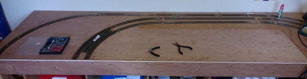
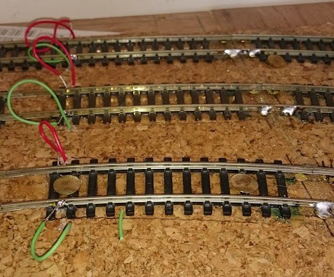
But up close.....
I'm having an internal debate at the moment about the layout of the track on the upper board - more of that later - but I reasoned I needed to get the inclines in before I can really make up my mind on that, so time to bite the bullet and get on with it.
In a production line ( in the shed) I cut out the plywood reinforcements for the baseboard joints where the inclines would either butt up to the next board or cross it.
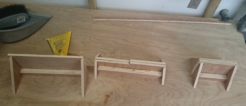
These were then glued and screwed in place and the inclines trimmed to fit.
 Flickr

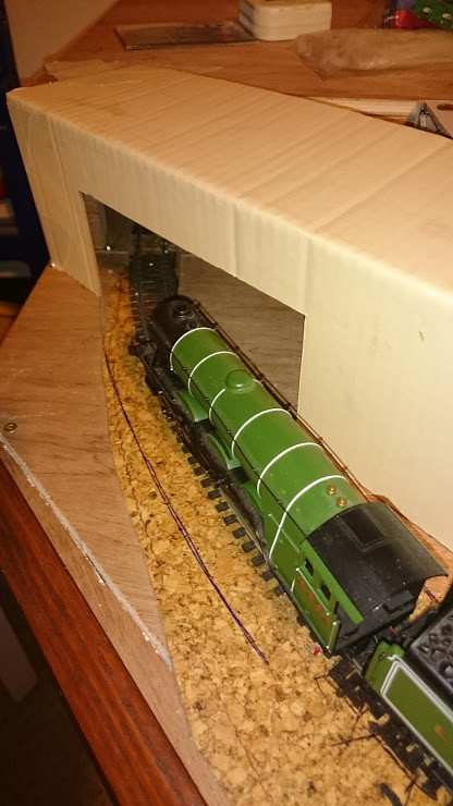
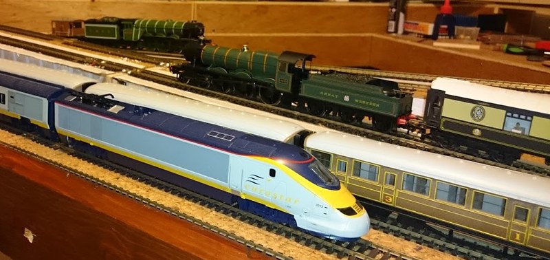
The Bridge desk was roughly cut out and temporary track was then laid around the loops. Flying Scotsman and Eurostar were used for clearance tests.

Which led to the reminder of one of those jobs I had never got to - i.e. Eurostar got caught in a loop of wire in the tunnel, and I hadn't cut the access holes yet - Doh!
Lucky the Small Controller has small enough arms to reach in and get the loco.
Once I had dismantled the temporary track, out came the pencil, a couple of quick rough outlines and some pilot holes.

Then a quick attack with the Jigsaw and then we had two boards with access holes now, tidied up afterwards with some sandpaper.


I must put up some low "walls" in the tunnels to retain any really errant rolling stack that makes a concerted effort to hit the floor.
Over a couple of evenings, when I had 20 minutes to spare, I got out the soldering iron and worked my way though the remaining main loop lines in the tunnels.
not much to see for my work from here;
But up close.....
I'm having an internal debate at the moment about the layout of the track on the upper board - more of that later - but I reasoned I needed to get the inclines in before I can really make up my mind on that, so time to bite the bullet and get on with it.
In a production line ( in the shed) I cut out the plywood reinforcements for the baseboard joints where the inclines would either butt up to the next board or cross it.
These were then glued and screwed in place and the inclines trimmed to fit.
FlickrThe Bridge desk was roughly cut out and temporary track was then laid around the loops. Flying Scotsman and Eurostar were used for clearance tests.
Which led to the reminder of one of those jobs I had never got to - i.e. Eurostar got caught in a loop of wire in the tunnel, and I hadn't cut the access holes yet - Doh!
Lucky the Small Controller has small enough arms to reach in and get the loco.
Once I had dismantled the temporary track, out came the pencil, a couple of quick rough outlines and some pilot holes.
Then a quick attack with the Jigsaw and then we had two boards with access holes now, tidied up afterwards with some sandpaper.
I must put up some low "walls" in the tunnels to retain any really errant rolling stack that makes a concerted effort to hit the floor.
Getting back into railways, one step at a time.
Ned's Workbench - https://tinyurl.com/y4jby73c
The UppydownyRoundyRoundyRailway - https://tinyurl.com/y6stelsr
Ned's Workbench - https://tinyurl.com/y4jby73c
The UppydownyRoundyRoundyRailway - https://tinyurl.com/y6stelsr
-
NedFlanders
- Posts: 184
- Joined: Mon Feb 01, 2016 7:56 pm
Some cardboard mock-ups, starting the powerbase and small jobs
Not much to report over the last two weeks, still tipping away at the list
After getting the inclines in, I laid cork down on the trackbed. The cork I have is some self adhesive floor tiles, which was all that was in stock nearby when I started laying track. As I was in the horrors of the glue on them reacting with the foam riser ( either straight away or some time in the future) I flipped them, and glued them down with the woodland scenics Foamtack glue on the plain cork side down with the self adhesive side up. The reasoning was that i could use the self adhesive side to stick the track to and the initial layer of ballast.
Cork laying in progress - Shiny white paper side up.

I also tested the damaged three way point ( see my point bar cutting escapades earlier) with a capacitor discharge unit - CDU - and it worked fine so at least I dont have to pull that up. no photo for this one.
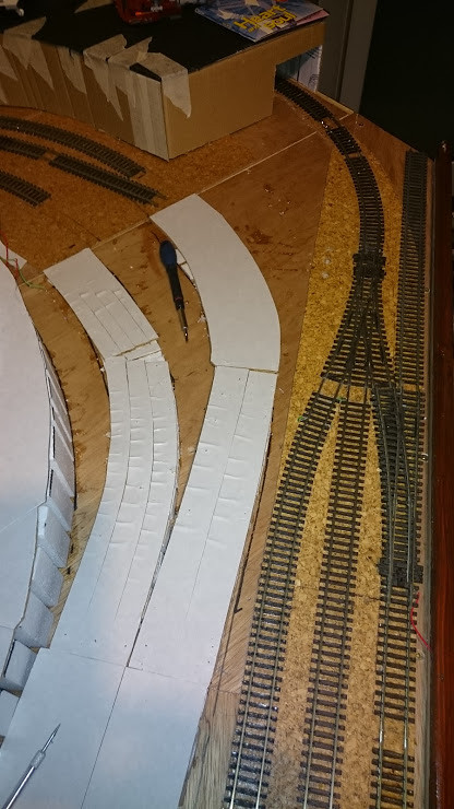
After watching a couple of Budget Model Railway videos ( look them up on you tube if you haven't come across them) I mocked up an angled tunnel entrance on the left side of the diagonal.
And a raised station area to the right of the lower station. This, I hope, will help disguise the worst of the sharp curve on the Island platform and give a bit more townscape scenery development opportunity here. currently its used to house completed Lego kits in between regular dismantling and recreation. Expect this to come more around the curve and also for some Wordsworth Kits to arrive as we see what works.

Tiring of the bunny border I printed out a selection of Wordsworth railway backscenes to hide the border and to get a feel for what might work behind the upper level station. I also printed out a photo of the Castle Folly to scale size to see how that looked, along with some test walls to see what colours/sizes we liked.

Then finally I started laying the Powerbase on the Inner-Inner line on the self Adhesive tiles.

After that I laid laid a point on top of the track on the outer storage line to get a feel for the potential TMD branch in the TV corner. I'm thinking of relocating the the turntable etc from the upper station to here as it gives more scenery space on the upper board, and I think it will end up as a display TMD for Locos more than an active element. I'd like to have it at the toe of the the three way point but I think that would lead to high speed derailments - having it on the outer loop would potentially compromise stock on the loop, but as that loop ostensibly is for traffic going away from the point it wouldnt have the derailment issue. plus as it will be used mostly as a display element I'm not sure the point will get musch use anyway - one for more future pondering.
As an aside - take a look here for some photos of a visit to a recreation of a rather unique railway that ran in Co. Kerry during the Height of the railway age. The Lartique Monorail - viewtopic.php?f=25&t=54633
Later,
Ned.
After getting the inclines in, I laid cork down on the trackbed. The cork I have is some self adhesive floor tiles, which was all that was in stock nearby when I started laying track. As I was in the horrors of the glue on them reacting with the foam riser ( either straight away or some time in the future) I flipped them, and glued them down with the woodland scenics Foamtack glue on the plain cork side down with the self adhesive side up. The reasoning was that i could use the self adhesive side to stick the track to and the initial layer of ballast.
Cork laying in progress - Shiny white paper side up.
I also tested the damaged three way point ( see my point bar cutting escapades earlier) with a capacitor discharge unit - CDU - and it worked fine so at least I dont have to pull that up. no photo for this one.
After watching a couple of Budget Model Railway videos ( look them up on you tube if you haven't come across them) I mocked up an angled tunnel entrance on the left side of the diagonal.
And a raised station area to the right of the lower station. This, I hope, will help disguise the worst of the sharp curve on the Island platform and give a bit more townscape scenery development opportunity here. currently its used to house completed Lego kits in between regular dismantling and recreation. Expect this to come more around the curve and also for some Wordsworth Kits to arrive as we see what works.
Tiring of the bunny border I printed out a selection of Wordsworth railway backscenes to hide the border and to get a feel for what might work behind the upper level station. I also printed out a photo of the Castle Folly to scale size to see how that looked, along with some test walls to see what colours/sizes we liked.
Then finally I started laying the Powerbase on the Inner-Inner line on the self Adhesive tiles.
After that I laid laid a point on top of the track on the outer storage line to get a feel for the potential TMD branch in the TV corner. I'm thinking of relocating the the turntable etc from the upper station to here as it gives more scenery space on the upper board, and I think it will end up as a display TMD for Locos more than an active element. I'd like to have it at the toe of the the three way point but I think that would lead to high speed derailments - having it on the outer loop would potentially compromise stock on the loop, but as that loop ostensibly is for traffic going away from the point it wouldnt have the derailment issue. plus as it will be used mostly as a display element I'm not sure the point will get musch use anyway - one for more future pondering.
As an aside - take a look here for some photos of a visit to a recreation of a rather unique railway that ran in Co. Kerry during the Height of the railway age. The Lartique Monorail - viewtopic.php?f=25&t=54633
Later,
Ned.
Getting back into railways, one step at a time.
Ned's Workbench - https://tinyurl.com/y4jby73c
The UppydownyRoundyRoundyRailway - https://tinyurl.com/y6stelsr
Ned's Workbench - https://tinyurl.com/y4jby73c
The UppydownyRoundyRoundyRailway - https://tinyurl.com/y6stelsr
-
NedFlanders
- Posts: 184
- Joined: Mon Feb 01, 2016 7:56 pm
September was slooooooow.
Well, September went fast and the progress was slooooow.
Didn't get much headway - and I've confirmed that I don't like laying track on inclines!
After getting the inclines stuck down and the cork roadbed in place I couldn't face laying/wiring the track on it. As I looked at the baseboard joint at the centre of the diagonal it hit me that I had generated a substantial rod for my back! Not sure when I thought having 7 tracks at three different levels going across a baseboard joint was a good idea.
So, the design philosophy was for this layout was: "Dad, can we have bridges and tunnels on this one?" (& I hate monolith baseboards that can never be moved).
As I understood it, best practice is:
1. Attach rails to brass screws or copper clad sleepers at the joints - agreed and confirmed with bitter previous experience.
2. Attach power feeds to each length of track - Grudgingly I will give you that one, I accept the pitfalls that may happen if you don't.
3. inclines should have transition slopes - yes I understand and accept that.
4. steep inclines need assistance for standard locos - yup! (Powerbase or extra weight etc.)
Pain for number 1. I should have allowed for the screws by having thicker baseboard joints timber - such a pain to get a decent size brass screw into 9mm.
Pain for number 2 - for the baseboard joints my experience suggests that the track panel just at the baseboard joint should be relatively short so that if you do damage the rail at the joint you dont have much track to repair- however, for a 1 yard length of track going across a baseboard joint that means 8 wires need to be soldered as it will end up being cut into four lengths ultimately!
Pain for number 3. I decided to use the woodland scenics inclines to avoid any hassles doing the slopes with plywood - on mature reflection ( with my tight curves) plywood is probably easier for double track. on the curves one incline needs to be shorter/longer than the other - or the track beds are not at the same height. I tried to get around this by gently compressing one side and stretching the other. Not completely successfully, it will work fine but next time for double track inclines with curves i will go for plywood or one woodland scenic incline with a twin track wide plywood road bed. Single track inclines i would be happy to use the woodland scenics on their own with a cork roadbed.
Pain for number 4. I was too concerned with the type of glue for the foam and i only had preglued cork flooring tiles - I laid it glue side up as I wasnt sure in the long term how the foam would like its contact adhesive. The Powerbase plates, laid on the glue side of the cork, started curling up at the "fish tail" and I superglued down any that did. some toyed with me and waited weeks before curling up. perhaps if I had laid the track quickly this wouldn't have been an issue. for the second incline I roughed up both sides of the powerbase with a coarse sandpaper and that side stuck to the preglued cork much better.
Back to the positive side though;
I indulged in some retail therapy - Two locos are on the way, one a second hand class 60 and the other a Christmas present with Irish connections. A couple of scenic bits and bobs , track ballast, ballast spreader, paints etc.
I experimented with a couple more Wordsworth printouts.
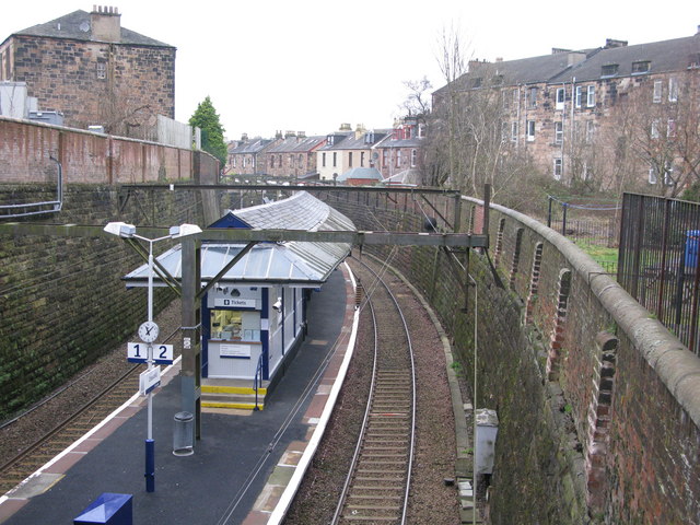
A trial of some terrace houses with a retaining wall below giving the impression of Crosshill station on the Cathcart line in Scotland which I finally found again ( This station is the inspiration for the lower level island station)
The real thing

The Wordsworth Terrace

I extended the mockup of TV corner raised area to see how that would look, and it hides nicely the curve on the far right of the board. For example Flying Scotmans nose only just appears as the last coach disappears so the curve looks "less silly".

One step at a time I gradually had most of the incline track prewired for fitting last weekend - I just could not raise the enthusiasm to start laying it.
( 7 tracks, three different levels, at a baseboard joint)
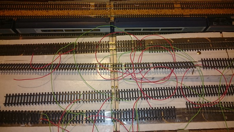
After a swift virtual kicking of myself by myself I knuckled down, aided by the Small Controller, and we got the job done.

Then the rails were soldered to the screws at the baseboard joints and then cut, The diagonal was dismantled and the boards put on their sides and the wiring tidied up. some nice symmetry here.

The acid test was performed by reconnecting the diagonal back in without doing any fine adjustments (i.e. trusting the locating pins) and Eurostar, Ketley hall and Flying Scotsman were sent around the three loops for a good hour - no derailments - all good! (There are two baseboard joint rail crossings that I'm not 100% happy with - but the trains dont seem to mind - one is a curve that during the track laying seems to have become less of a curve'and the other is a joint where, for some reason, I forgot my rule to not have a peice of settrack finishing at a board joint - i.e. the transition to the incline is abrupt - I'll see if I can get a photo later to explain better)
Next up is some ballast testing, some platform making, magnet fitting some more locos for the Powerbase and some more trial backscenes as they really make it feel like a corner has been turned.
Cheerio,
Ned.
Didn't get much headway - and I've confirmed that I don't like laying track on inclines!
After getting the inclines stuck down and the cork roadbed in place I couldn't face laying/wiring the track on it. As I looked at the baseboard joint at the centre of the diagonal it hit me that I had generated a substantial rod for my back! Not sure when I thought having 7 tracks at three different levels going across a baseboard joint was a good idea.
So, the design philosophy was for this layout was: "Dad, can we have bridges and tunnels on this one?" (& I hate monolith baseboards that can never be moved).
As I understood it, best practice is:
1. Attach rails to brass screws or copper clad sleepers at the joints - agreed and confirmed with bitter previous experience.
2. Attach power feeds to each length of track - Grudgingly I will give you that one, I accept the pitfalls that may happen if you don't.
3. inclines should have transition slopes - yes I understand and accept that.
4. steep inclines need assistance for standard locos - yup! (Powerbase or extra weight etc.)
Pain for number 1. I should have allowed for the screws by having thicker baseboard joints timber - such a pain to get a decent size brass screw into 9mm.
Pain for number 2 - for the baseboard joints my experience suggests that the track panel just at the baseboard joint should be relatively short so that if you do damage the rail at the joint you dont have much track to repair- however, for a 1 yard length of track going across a baseboard joint that means 8 wires need to be soldered as it will end up being cut into four lengths ultimately!
Pain for number 3. I decided to use the woodland scenics inclines to avoid any hassles doing the slopes with plywood - on mature reflection ( with my tight curves) plywood is probably easier for double track. on the curves one incline needs to be shorter/longer than the other - or the track beds are not at the same height. I tried to get around this by gently compressing one side and stretching the other. Not completely successfully, it will work fine but next time for double track inclines with curves i will go for plywood or one woodland scenic incline with a twin track wide plywood road bed. Single track inclines i would be happy to use the woodland scenics on their own with a cork roadbed.
Pain for number 4. I was too concerned with the type of glue for the foam and i only had preglued cork flooring tiles - I laid it glue side up as I wasnt sure in the long term how the foam would like its contact adhesive. The Powerbase plates, laid on the glue side of the cork, started curling up at the "fish tail" and I superglued down any that did. some toyed with me and waited weeks before curling up. perhaps if I had laid the track quickly this wouldn't have been an issue. for the second incline I roughed up both sides of the powerbase with a coarse sandpaper and that side stuck to the preglued cork much better.
Back to the positive side though;
I indulged in some retail therapy - Two locos are on the way, one a second hand class 60 and the other a Christmas present with Irish connections. A couple of scenic bits and bobs , track ballast, ballast spreader, paints etc.
I experimented with a couple more Wordsworth printouts.
A trial of some terrace houses with a retaining wall below giving the impression of Crosshill station on the Cathcart line in Scotland which I finally found again ( This station is the inspiration for the lower level island station)
The real thing
The Wordsworth Terrace
I extended the mockup of TV corner raised area to see how that would look, and it hides nicely the curve on the far right of the board. For example Flying Scotmans nose only just appears as the last coach disappears so the curve looks "less silly".
One step at a time I gradually had most of the incline track prewired for fitting last weekend - I just could not raise the enthusiasm to start laying it.
( 7 tracks, three different levels, at a baseboard joint)
After a swift virtual kicking of myself by myself I knuckled down, aided by the Small Controller, and we got the job done.
Then the rails were soldered to the screws at the baseboard joints and then cut, The diagonal was dismantled and the boards put on their sides and the wiring tidied up. some nice symmetry here.
The acid test was performed by reconnecting the diagonal back in without doing any fine adjustments (i.e. trusting the locating pins) and Eurostar, Ketley hall and Flying Scotsman were sent around the three loops for a good hour - no derailments - all good! (There are two baseboard joint rail crossings that I'm not 100% happy with - but the trains dont seem to mind - one is a curve that during the track laying seems to have become less of a curve'and the other is a joint where, for some reason, I forgot my rule to not have a peice of settrack finishing at a board joint - i.e. the transition to the incline is abrupt - I'll see if I can get a photo later to explain better)
Next up is some ballast testing, some platform making, magnet fitting some more locos for the Powerbase and some more trial backscenes as they really make it feel like a corner has been turned.
Cheerio,
Ned.
Getting back into railways, one step at a time.
Ned's Workbench - https://tinyurl.com/y4jby73c
The UppydownyRoundyRoundyRailway - https://tinyurl.com/y6stelsr
Ned's Workbench - https://tinyurl.com/y4jby73c
The UppydownyRoundyRoundyRailway - https://tinyurl.com/y6stelsr
-
NedFlanders
- Posts: 184
- Joined: Mon Feb 01, 2016 7:56 pm
Trackwork Rationialisation
Trackwork developments
Its been a while, the trains had to take a back seat for a bit but every now and then a few things got done - here's some trackwork news.
TV corner was going to become available for "Train Table" expansion so the trackwork for the upper station was rationalized.
Originally there was due to be a turntable and outside loop for locomotive swapping and a full inside goods yard with a loop that would double as a shunting puzzle - see here ( Apologies for the poor quality of the image ).
The thoughts behind the design changes were - More scenery was being requested, was there really room to operate two shunting puzzles in the central well? We need a Castle!
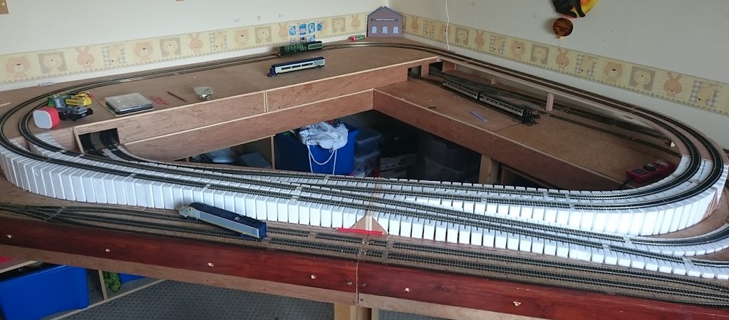
Anyhow, this is what we've ended up with at the upper level.
The Island platform is replaced by two single platforms, the inside one will curve to the start of the bridge. The two sidings will fit four car Container trains with just enough room for a class 26 to not foul the mainline. I think this will become a small intermodal yard with a Reach and Stack "forklift" in operation as a crane would dominate it too much. This would then leave room for more scenic development at the top of the incline. I did debate putting the point on the incline but I felt it might present more problems than solutions and remove most of the scenic opportunity at the top of the incline as the line would have to curve through the scenic area.
In a similar vein the goods yard at the lower yard has also seen rationalization - the loop is gone, and the sidings are in from the edge to give a bit more scope for scenery.
These sidings will allow for a 3-2-2 inglenook with the headshunt heading into the tunnel. I may make this an interchangeable "industry" depending on what the small controller wants to mess with on a given day. Heres what it looks like with a three car train in the long siding.
Cheerio all.
Ned.
Its been a while, the trains had to take a back seat for a bit but every now and then a few things got done - here's some trackwork news.
TV corner was going to become available for "Train Table" expansion so the trackwork for the upper station was rationalized.
Originally there was due to be a turntable and outside loop for locomotive swapping and a full inside goods yard with a loop that would double as a shunting puzzle - see here ( Apologies for the poor quality of the image ).
- Original upper plan.JPG (19.39 KiB) Viewed 3181 times
Anyhow, this is what we've ended up with at the upper level.
In a similar vein the goods yard at the lower yard has also seen rationalization - the loop is gone, and the sidings are in from the edge to give a bit more scope for scenery.
Ned.
Getting back into railways, one step at a time.
Ned's Workbench - https://tinyurl.com/y4jby73c
The UppydownyRoundyRoundyRailway - https://tinyurl.com/y6stelsr
Ned's Workbench - https://tinyurl.com/y4jby73c
The UppydownyRoundyRoundyRailway - https://tinyurl.com/y6stelsr
-
NedFlanders
- Posts: 184
- Joined: Mon Feb 01, 2016 7:56 pm
Baseboard joint problems
So back last Autumn I was busy laying and cutting the various baseboard joints and having varying degrees of success, and there are a few running issues I must address before all the ballasting can take place.
This base board joint appears to have lost its transition gradient. If a loco is going slowly from right to left sometimes they stall on the joint as the incline starts abruptly. I have exaggerated it with the red lines - but as an example, if a tender drive loco like Flying Scotsman is going slowly over it, when the leading axle of the tender goes across the joint it stops with wheels spinning as it doesn't have enough contact/adhesion with the rails. I'm going to see if I just lay a powerbase plate under the section to the right will that sort it.
This curve on a joint seemed to go all out of true when being soldered, the trains run fine through it, but it annoys me immensely to see the locos go straight for two inches and then go around the curve again, its hard to see in this photo but the red line shows the section where the curve is less curved than the rest of the curve ( way too many curves in that sentence).
This upper joint seemed to always derail the leading wheels of Mallard so I thought the gradient change might have been abrupt as well so I elongated the transition to the gradient here and then discovered the issue is probably that I seem to have a bad solder on the outside rail which allows it to go out of gauge ( tightens) by less than half a millimeter in the direction of the arrow - doh. A quick resolder and all was fine again until the solder failed again so I must have a badly prepared screwhead or bad application - I will redo it from scratch.
All that said, if I have problems with 3 out of 21 I'll take that, especially as the issues seem easily sorted.
Cheerio.
Ned.
This base board joint appears to have lost its transition gradient. If a loco is going slowly from right to left sometimes they stall on the joint as the incline starts abruptly. I have exaggerated it with the red lines - but as an example, if a tender drive loco like Flying Scotsman is going slowly over it, when the leading axle of the tender goes across the joint it stops with wheels spinning as it doesn't have enough contact/adhesion with the rails. I'm going to see if I just lay a powerbase plate under the section to the right will that sort it.
- NoCurve.JPG (87.1 KiB) Viewed 3165 times
Cheerio.
Ned.
Getting back into railways, one step at a time.
Ned's Workbench - https://tinyurl.com/y4jby73c
The UppydownyRoundyRoundyRailway - https://tinyurl.com/y6stelsr
Ned's Workbench - https://tinyurl.com/y4jby73c
The UppydownyRoundyRoundyRailway - https://tinyurl.com/y6stelsr
-
NedFlanders
- Posts: 184
- Joined: Mon Feb 01, 2016 7:56 pm
Bunk Beds, etc.
There have been some other developments.
The first bit of ballasting was done ( Back in Sept/Oct, after first trying some on scrap board). I did the storage loops in 7 phases, to allow me to see what worked and what didn't. I did half a storage road at a time for the first 6 attempts, gradually reducing the amount of ballast used ( i.e. the first couple of lines had ballast that was turning out to be just above the level of the sleepers), and then the final phase was the turnouts and the curves into the tunnels.
I also did a spot of maintenance on a HST belonging to a friend. It hadn't run in 20-25 years and he wanted to use ( play) with his son. I replaced the carbon brush and the spring that were missing and gave the gears etc. a clean and light oil and away she flew.
As you can see in the background I have printed out some retaining walls and I am checking out how the buttresses look depending on spacing and thickness. A lima Class 60 that I picked up is peeking over the top. Also, I haven't got back to clearing off the errant ballast on the sleepers.
The storage for the diagonal boards had been annoying me as it was a long finger job so I finally got around to making their bunk beds. ( A lot of cabling needs to be tided up at the next dismantling)
and the diagonal boards in bed.
on the Curved Joint, I sorted out the curve that wasn't ( see previous post).
Onwards and upwards - I must redo the temporary bridge deck over the lower station with the final shape - a bit of bodging will be needed as the Eurostars are a bit close on the curve to the abutments at TV corner.
Until next time.
Ned.
The first bit of ballasting was done ( Back in Sept/Oct, after first trying some on scrap board). I did the storage loops in 7 phases, to allow me to see what worked and what didn't. I did half a storage road at a time for the first 6 attempts, gradually reducing the amount of ballast used ( i.e. the first couple of lines had ballast that was turning out to be just above the level of the sleepers), and then the final phase was the turnouts and the curves into the tunnels.
The storage for the diagonal boards had been annoying me as it was a long finger job so I finally got around to making their bunk beds. ( A lot of cabling needs to be tided up at the next dismantling)
Until next time.
Ned.
Last edited by NedFlanders on Wed Jan 29, 2020 11:12 am, edited 1 time in total.
Getting back into railways, one step at a time.
Ned's Workbench - https://tinyurl.com/y4jby73c
The UppydownyRoundyRoundyRailway - https://tinyurl.com/y6stelsr
Ned's Workbench - https://tinyurl.com/y4jby73c
The UppydownyRoundyRoundyRailway - https://tinyurl.com/y6stelsr
Re: UppyDownyRoundyRoundyRailway
An interesting read Ned, I cannot believe that no one else has replied to your posts
Re: UppyDownyRoundyRoundyRailway
Maybe it is because we are all UppyDownyRoundyRoundy.Stainsacre wrote: I cannot believe that no one else has replied to your posts
An amazing layout indeed.
Glencairn
To the world you are someone. To someone you are their world.
I Cannot Afford the Luxury of a Negative Thought
I Cannot Afford the Luxury of a Negative Thought
-
TimberSurf

- Posts: 2537
- Joined: Wed Jan 08, 2014 5:47 pm
- Location: N.Wales
- Contact:
Re: UppyDownyRoundyRoundyRailway
I do think other forums that have the capability to put a "like" against a post, encourages the poster that at least someone is reading the content and appreciating it. Without that ability, its hard to just put repeated platitudes every time a new post is added, as it seems somewhat wasteful of the forum and may not serve much of a purpose other than letting the poster know his dialogue and adventures are being enjoyed.
That said, I do follow this thread and think, said poster is very brave attempting a multi level dismantleable layout and doing a damned good job. The text says it all.
I hope to follow in your footsteps once I get a room big enough for the final Lumsdonia design and will have similar multi level modular joined sections (but hope not to have to dismantle too often, just for maintenance etc)

-
NedFlanders
- Posts: 184
- Joined: Mon Feb 01, 2016 7:56 pm
Re: UppyDownyRoundyRoundyRailway
Hi all,
Thanks for the comments.
I too have felt that a "Like" button wouldn't be the worst addition to the forum, that said, after a while I noticed the read counter for the threads, and in my mind, that equates to a barometer of "Like". If people are still reading, then I will keep posting my progress.
As I was getting back into the hobby one of the things that gave me the most enjoyment was finding a thread of someone starting a layout and working their way through it to its nominal completion, or they were in the middle of it and I would happily follow it ( penguins table top n gauge layout springs to mind as an example - if my memory serves me right). Quite often though, many threads would be long dead but the experience was all there - thus any comment I might make would be perhaps meaningless.
When I started this thread I hoped it might end up the same way for someone else at some point, as well as acting as a means of getting advice/constructive criticism which is something I felt this forum excels at when compared to some of the other sites out there. If nothing else, posting to this thread would also act as an encouragement for me to keep going which would help me to get the layout to its natural conclusion, for good or bad.
So, thanks for the reads, any comments/advice, and happy modelling everyone.
Cheery-bye neighbours,
Ned.
Getting back into railways, one step at a time.
Ned's Workbench - https://tinyurl.com/y4jby73c
The UppydownyRoundyRoundyRailway - https://tinyurl.com/y6stelsr
Ned's Workbench - https://tinyurl.com/y4jby73c
The UppydownyRoundyRoundyRailway - https://tinyurl.com/y6stelsr
Re: UppyDownyRoundyRoundyRailway
I agree, as Timbersurf says it seems a bit pointless to keep saying, “that looks nice” and as you say the 'barometer of like' is the number of views.
I had a thread detailing my N gauge layout build that I sold back in March last year. In September I received a PM from a new member saying he had come across my layout and was planning something similair he said would like to copy my build, very flattering for me but more importantly I was able to give him a lot of information and advice to get him started.
My latest layout thread is my OO gauge layout that I began building in March, I started the thread with the bare board, the idea being that as I have gained more experience newcomers to the hobby can learn from it. That's not to say I'm the greatest modeler by any means but when I started out with no knowledge at all of modeling I found this forum I took inspiration from a number of different layouts and over the years have received a lot of good advice without which I would have given up long ago. and now hope I can pass some of that knowledge on.
Dave
-
PinkNosedPenguin

- Posts: 1683
- Joined: Tue Oct 01, 2013 10:23 pm
- Location: Wiltshire
Re: UppyDownyRoundyRoundyRailway
Thanks NedNedFlanders wrote:... ( penguins table top n gauge layout springs to mind as an example - if my memory serves me right)...
Ned.
I am following your thread, but as others have said not always commenting, but following nevertheless.
I have now moved on and changed scale
-
NedFlanders
- Posts: 184
- Joined: Mon Feb 01, 2016 7:56 pm
Lower Bridge Abutments Cutback
So now that I knew I would have to cut back the Bridge abutments on the right of the lower station before I could complete the track laying, I cracked on with some Civil engineering:
The two yellow lines show the old line of the abutment and the new line. To cut it back I used a full size hacksaw blade ( not the junior blade), to first cut back under the cork trackbed layer and then to cut straight down, it gave a relatively clean cut line - happy engineer. The red arrow shows a complication - this is the clearance line for the Eurostar coaches - The retaining wall will have to be out to this line with filler behind it in order to accommodate them.
Some quick Clearance tests - and still happy. While the length of them is a pain, I'm glad we bought the eurostar coaches before I had the track completed as they are astonishingly long compared to the other coaches.
As I felt that leaving the curved track in place rather than cutting them to the new bridge edge would allow me to seamlessly continue the track on the curved bridge deck, I'm surprised that either I have managed to miss catching anything on them over the week or that the track is so well stuck down that none of my elbows managed to do any damage.  Some of the other weeks work was some more buildings for TV corner - Building trials and tribulations are detailed on my workbench page (link in my signature below) but here's a family photo.
Now to some bridge work.
Some of the other weeks work was some more buildings for TV corner - Building trials and tribulations are detailed on my workbench page (link in my signature below) but here's a family photo.
Now to some bridge work.
Ned.
Some quick Clearance tests - and still happy. While the length of them is a pain, I'm glad we bought the eurostar coaches before I had the track completed as they are astonishingly long compared to the other coaches.
Ned.
Getting back into railways, one step at a time.
Ned's Workbench - https://tinyurl.com/y4jby73c
The UppydownyRoundyRoundyRailway - https://tinyurl.com/y6stelsr
Ned's Workbench - https://tinyurl.com/y4jby73c
The UppydownyRoundyRoundyRailway - https://tinyurl.com/y6stelsr
-
NedFlanders
- Posts: 184
- Joined: Mon Feb 01, 2016 7:56 pm
Final Bridge deck
The bridge deck was the next to be looked at.
I laid a motley collection of thick card on the existing deck until I had all the area of the bridge deck covered - masking tape was used to keep them together.
Some temporary track was laid to get the clearance lines for the bridge deck, and the eurostar Loco was used for the outside line as it has the most front overhang.
And the Eurostar coaches were used for the inside line clearance
The card was cut to outside the clearance lines and then test fitted back before cutting any plywood
I used the card template to then lay out the lines on the plywood and after a bit of jigsawing later we have the new deck in place.
The red arrows show where the supports for the plate girder sections will be, and in the grand tradition of a prototype for everything I have found photos of curved plate girder bridges so after my inital misgivings on doing that I'm happy to go that route on the right hand side of the bridge.
The left hand side of the bridge does not allow me to plate girder sections there as the span would be too long- in my view, so I have mocked up on the photo the outline of a grey truss bridge. This may change later, but we'll see how it goes as things progress.
Now as the bridge deck is off - time for some platforms.
Onwards Navvies!
I laid a motley collection of thick card on the existing deck until I had all the area of the bridge deck covered - masking tape was used to keep them together.
The left hand side of the bridge does not allow me to plate girder sections there as the span would be too long- in my view, so I have mocked up on the photo the outline of a grey truss bridge. This may change later, but we'll see how it goes as things progress.
Now as the bridge deck is off - time for some platforms.
Onwards Navvies!
Getting back into railways, one step at a time.
Ned's Workbench - https://tinyurl.com/y4jby73c
The UppydownyRoundyRoundyRailway - https://tinyurl.com/y6stelsr
Ned's Workbench - https://tinyurl.com/y4jby73c
The UppydownyRoundyRoundyRailway - https://tinyurl.com/y6stelsr