Wiring Facing Electrofrogs

Basic electrical and electronics, such as DC/Analog control.
Post Reply
whynot
Posts: 1946
Joined: Fri Jul 09, 2010 3:37 pm
Location: Nottingham

Wiring Facing Electrofrogs

Post by whynot »

Before I simply consign the lot to the skip, can anyone tell me - in simplest of terms please! - why the junction on my 0 16.5 just won't seem to work? I've redone the actual (untidy but very basic) wiring three times and I have done electrofrog cross overs numerous times, but...

THIS NO MAKES NO SENSE BECAUSE THE TEXT WAS FOR A PHOTO ROTATED CLOCKWISE WHICH SEEMS TO HAVE FAILED! I'LL TRY AGAIN LATER!

(LH and RH by reference to the photo) LH point and bottom RH are separated by IRJs and I hope you can see where the feeds are. The bottom track(s) simply go dead when the LH and the bottom RH are switched towards each other even when no power applied to the LH. From ignorance and desperation I cut the wires beneath the frogs (I assume) on the RH - did allow the bottom tracks to run whichever way it was switched but not when LH powered.

Image

Reading this I suspect doesn't make sense! I'm sure I've followed same principles with older(?) 00 versions of these points with no problem - I've never added additional wiring, motors, polarity (?) switches etc.

Any and all advice welcome!
RFS
Posts: 947
Joined: Tue Jan 12, 2010 3:09 pm
Location: Derbyshire, UK

Re: Wiring Facing Electrofrogs

Post by RFS »

You need IRJs (Insulated Rail Joiners) on each of the vee-rails with feeds at the heel end of the turnouts. 6 joiners in total - 2 on each point.

Unless you're going to fit a polarity switch you should not have cut any wires under the frog. If you have, you'll now have some dead section of rail. So you may need to replace them.
Robert Smith
whynot
Posts: 1946
Joined: Fri Jul 09, 2010 3:37 pm
Location: Nottingham

Re: Wiring Facing Electrofrogs

Post by whynot »

"You need IRJs (Insulated Rail Joiners) on each of the vee-rails with feeds at the heel end of the turnouts. 6 joiners in total - 2 on each point."

Thanks, but that's the bit I don't understand! The feed at the heel of the point on the left works just fine for both the sidings leading off the top RH point without any IRJs. There is a feed at the end of the top RH siding but it is isolated from feeding back into the frog by IRJs in both rails part way along the siding. It will all presumably work OK if I also just run a siding off the LH point rather than another point - if I lose the kick back then I could just have a 3 siding Inglenook

But I have certainly wasted two points by cutting the wires. Expensive morning's work....30 quids worth of points that I can't really afford to replace simply to experience the same problem. Project abandoned I think.
User avatar
flying scotsman123
Posts: 2233
Joined: Thu Jan 12, 2012 5:29 pm
Location: err, down there round the corner... not that one!!!

Re: Wiring Facing Electrofrogs

Post by flying scotsman123 »

whynot wrote: But I have certainly wasted two points by cutting the wires. Expensive morning's work....30 quids worth of points that I can't really afford to replace simply to experience the same problem. Project abandoned I think.
You haven't ruined the points though, just made them unsuitable for a certain type of operation. I suppose you could either wire up for polarity switching yourself or flog them on eBay to someone who will. Don't give up! :)
Image
Stone station in pre-grouping days, my layout. Workbench for other projects here.
RFS
Posts: 947
Joined: Tue Jan 12, 2010 3:09 pm
Location: Derbyshire, UK

Re: Wiring Facing Electrofrogs

Post by RFS »

With Electrofrog points the whole frog area - from tip of the blades to the end of the vee rail is one piece of metal. So all you need to do to fix the points where you cut the wires is to put one wire to connect the rails on either side of the frog. You may need one wire for each vee rail. Then with IRJs on the 6 vee rails, and feeds at the heel end of all 3 points, you should find everything works.

To wire the frog for use with a polarity switch, you would need to actually cut the rails themselves, and I see you haven't done this.
Robert Smith
whynot
Posts: 1946
Joined: Fri Jul 09, 2010 3:37 pm
Location: Nottingham

Re: Wiring Facing Electrofrogs

Post by whynot »

Thanks both.

"Then with IRJs on the 6 vee rails, and feeds at the heel end of all 3 points, you should find everything works."

So, this WON'T work?

Image

Red and black are feeds, green IRJs. I can't see the need for 6 IRJs nor how to put feeds into the heel of a point leading off one of the diverging lines of another point without that "feeding" back into the frog.

Time for a different plan I guess!
RFS
Posts: 947
Joined: Tue Jan 12, 2010 3:09 pm
Location: Derbyshire, UK

Re: Wiring Facing Electrofrogs

Post by RFS »

Your solution will work only if the tracks top right, centre right and bottom left are dead-end sidings. If any of them continue on and have their own track feeds then you must put IRJs on their vee rails and provide track feeds downstream of their IRJs.
Robert Smith
whynot
Posts: 1946
Joined: Fri Jul 09, 2010 3:37 pm
Location: Nottingham

Re: Wiring Facing Electrofrogs

Post by whynot »

Well, yes, obviously all dead ends! Altho' two will have feeds to switchable loco release end sections, isolated from the point(s) by IRJs in each rail somewhere along the siding.

What I had followed this design and incorporated these principles and yet did not work - hence my puzzlement.

If I rule out faulty points, then the errors must I suppose be in the wiring loom.

Must start again...
User avatar
Bufferstop
Posts: 13822
Joined: Thu Mar 11, 2010 12:06 pm
Location: Bottom end of N. Warks line

Re: Wiring Facing Electrofrogs

Post by Bufferstop »

whynot wrote:Thanks both.
"Then with IRJs on the 6 vee rails, and feeds at the heel end of all 3 points, you should find everything works."
So, this WON'T work?
If the points blades are switching correctly and the links below the sleepers are as shipped it should work. All of the spurs will be isolated by the movement of the points. You may want to put a switch in the RH feed to allow a loco to stand in that section whilst another accesses the tracks at the top.

If you want to make it "DCC ready" go with the 6 IRJs dropers from all of the spurs and the frogs and temporarily connect the droppers from each spur to the one for the frog to make it self isolating. To convert it later to DCC would just mean rearranging the connections rather than having to put in extra wiring.
Growing old, can't avoid it. Growing up, forget it!
My Layout, My Workbench Blog and My Opinions
whynot
Posts: 1946
Joined: Fri Jul 09, 2010 3:37 pm
Location: Nottingham

Re: Wiring Facing Electrofrogs

Post by whynot »

Thanks.

Back to square 1.....disconnected all on/off switches and split wires at choc blocks and simply connected first the LH feed direct to controller (it worked) then the RH ditto (it worked) then both together and unlike 3-4 attempts yesterday loco ran fine through the top left to bottom right junction! And bottom left to bottom right. I shall have to buy a new point for top RH having wrecked two others! (Couple of CHEAP 0 16.5 Ys for repair anyone??)

Clearly fault in the loom - annoying but at least the principles were right, just the clumsy practice that was wrong. I must be more careful adding in isolating sections I guess.

Thanks all.

PS @Bufferstop, as is no doubt obvious I have trouble enough with DC, DCC is not an option I shall even consider! And I'm afraid your instructions simply dazed me.
b308
Posts: 5106
Joined: Sat Apr 15, 2006 5:48 pm
Location: North Worcs

Re: Wiring Facing Electrofrogs

Post by b308 »

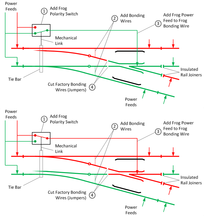
Dave, this shows what happens on live frog points when you switch the points, hope it helps explain why you need insulated joiners on facing points (crossovers)...

Image

I isolate every siding anyhow, I know I don't need to but it just makes life easier!:
whynot
Posts: 1946
Joined: Fri Jul 09, 2010 3:37 pm
Location: Nottingham

Re: Wiring Facing Electrofrogs

Post by whynot »

What a neat diagram! I've never had any problems before, simply following the basic rule of "no power into the frog end(s)" . I don't do soldering so I've always ignored the refinements beyond that basic rule - and it has worked. And the principle did work here - the fault was somewhere in the implementation.

I resisted my usual urge simply to bin the lot and started again, so at least my patience is improving.

Thank you all for YOUR patience and advice.
User avatar
Flashbang
Posts: 4092
Joined: Thu Oct 18, 2007 1:07 pm
Location: SE United Kingdom
Contact:

Re: Wiring Facing Electrofrogs

Post by Flashbang »

Not fitting two IRJs per point onto each Electrofrog point Vee rail ends, even when leading into a dead end siding, is really a poor practice. Fitting them takes seconds and all you need then is two new rail feeds after the IRJs, one of each polarity to the appropriate rail. If you want to make a DC layout have an isolated siding section then pass that rails feed via an On/Off switch. So regardless of the points position the switch controls the power to the siding.
While not fitting them into a dead end siding seems a simple answer, problems quickly occur if any later on additions are added to the track plan you can very quickly end up with a full short circuit occurring!
If the layout is currently DC and at some stage DCC might be considered in the future, even if its not considered at the present time, by adding the IRJs now it simply means the track work is ready and should need no further work. You shouldn't ever get shorting occurring with two IRJs per point Vee rail unless you run into an unset point! :o
[Image << Click the Icon to go to my website
Broken? It was working correctly when I left it.
whynot
Posts: 1946
Joined: Fri Jul 09, 2010 3:37 pm
Location: Nottingham

Re: Wiring Facing Electrofrogs

Post by whynot »

A useful and no doubt all true summary, but,in no particular order, 1. the track can never be extended given space considerations 2. DCC will never be considered on cost - (the whole point of 0 16.5 is it's cheapness, the whole layout is going to cost less than 1 DCC loco and a controller) and complexity grounds, 3. once it's "built" it will very probably either be broken down or sold complete - I have little interest in running trains and 4. I've never had any problems from this approach with last half dozen or so similarly simple layouts!

0 16.5 means I have to DIY locos and rolling stock - it really is just something to pass the time twixt now and when I "pass" (awful modern usage!).
Post Reply