

I have to say that this is coming along very nicely indeed. I've toyed with the idea of building this one but the cost put me off. I bet the total cost of your build will be eye-watering once you've finished !
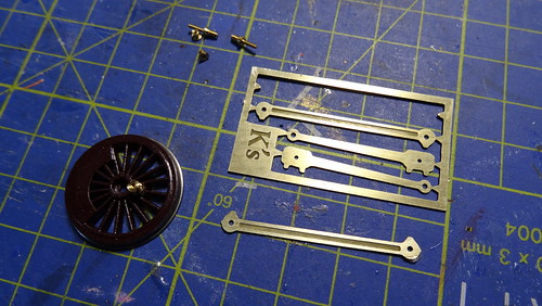
K's kits can require a staggering amount of fettling and substitution. I'm working on a so-called 57XX pannier currently and it's quite literally problems at every turn. When it's finished it won't even look that good by current standards either, which means that it's all down to added detail and good paintwork to lift the eye away from the crude and overscale castings ! Still, I need something with enough grunt to pull a heavy train of K's coaches.
Tony
BMR Workbench.
Re: BMR Workbench.
Men with false teeth may yet speak the truth.......
Re: BMR Workbench.
Thanks Tony for the comment. It is actually finished already but I just haven't got round to writing it up.
To be honest it is a bit of a nightmare to build like any K's Kit really.
First issue was both rods to the cylinders were 1.2mm too long so had to be shortened, holes re-drilled.
Total cost is not to bad considering, I have had to bin the original K's chassis which you will see later on, as no matter what I did it would not sit flat, or square... my suspicion is that one of the mounting holes at the front was a little out as all the screws were tight.
Anyway I found a spare chassis, that's built and is running a lot better.
Which will be part of my workbench video series which have gone down well so far.
Either way I think total to date is around £120... not including my time haha.
As I always say about K's they were a good idea at the time... some kits not to bad once some additional detail is fitted they do make some nice models, if you can work through the problems. Plus some newer chassis's are available now.
- Youtube/bluebellModelrailway
- https://railway-modeller-mw.weebly.com/
- VECTIS 3D: mademe.co.uk/shop/vectis-3d-models/
- https://railway-modeller-mw.weebly.com/
- VECTIS 3D: mademe.co.uk/shop/vectis-3d-models/
Re: BMR Workbench.
Next was to clean/ degrease the chassis in readiness for pickup strips to be a fitted, then the chassis can be primed ready for paint, red for the middle of the frames and matt black for the outside.
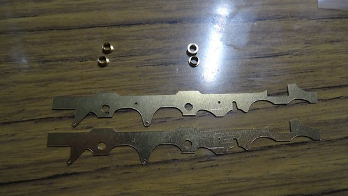
After the cleaning of the chassis I cut a strip copper clad board, measured out what I required, 2x 20mm for the front 2 wheels, and 2x 8mm for the rear wheels. These were then glued to the inside chassis with Araldite, when set these were covered ready for painting.
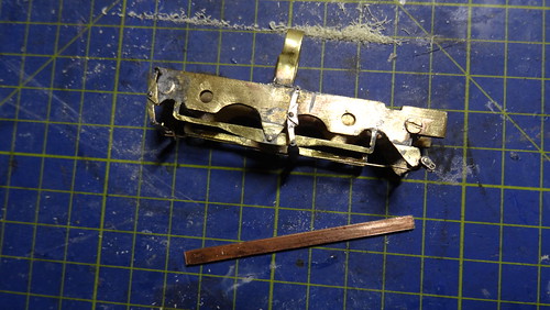
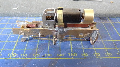
(Left: Pickup strip ready to be cut and fitted, Right: pickups fitted, plus motor / gearbox, plus the flywheel)
The chassis went for painting, meanwhile while this was drying the fun part began, lining, transfers arrived from Radley Models, sadly there is no certain transfer sheet for this model, Phil at Radley suggested the pannier lining sheet which I think also are the best suited, also ordered was a metropolitan insignia and numbers. These are just normal waterslide transfers so quite easy to deal with.
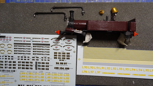
(Left: Transfers from Radley, using metropolitan insignia and pannier lining. Right: Lining being applied)

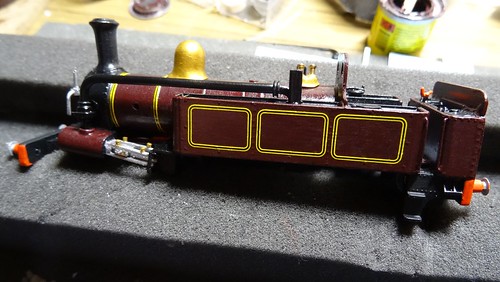
(Mostly completed lining still details and a little lining to do)
After a day and a bit the lining was mostly complete just a few areas on the front and rear of the cab these were then sealed in with a light coat of varnish (Vallejo Satin Acrylic). Once dry small parts were then added (clack valves, pipe work, lamp irons, back head)
But for now back to the chassis, more parts arrived from Peters spares Phosphor Bronze strip 3/64"x7 1/4" (M2) was ordered for the back scratch pickups, these were bent at a 90 degree angle soldered to the inside copper clad board and then bent again down the outside of the chassis to pickup from the back of the wheel.
The chassis was then wired up but couldn't be test run yet as there was still a few things to do.
So next job was the wheels and it's crank pins, not using the original wheels with the crankpins already fitted using the new wheels required new crank pins, I use on most of my kits the Romford deluxe crank pins, which are screwed in to the wheel, with the pin itself being tapped for a small collared nut this means the holes in the rods must be enlarged to take the new pins.
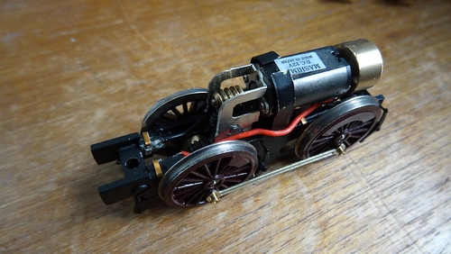
(Left: Romford deluxe crank pins, and rods. Right: The chassis mostly complete with trimmed flywheel + connection rods)
The chassis is test run to check for tight spots on the rods and crank pins there was a slight tight spot running in forward, so the rods need to be taken off and holes checked and opened up slightly to improve the running in forward.
While on the motion I found a problem with the next stage which is the connection rod between the wheel and cylinder slider, the problem became apparent when offering up the rod before fitting, the rod turned out to be 2mm to long which certain was a surprise. There isn't much material on the rod to drill another hole a bit further up but it's do-able if not it's quite easy to make a new rod from nickel silver sheet. The hole was moved back toward the wheel by 2mm, and a 0.7mm drill was used for the new hole, then de-burred to stop any catching or binding.
After the modification was done, the rest of the motion was re-assembled and it ran ok but it was obvious that something else was not quite right after some investigation I found the chassis was not square or aligned properly either through amounting point incorrectly drilled or fitted. More investigation needed.
(On test on the rolling road, checking for tight spots)
After the cleaning of the chassis I cut a strip copper clad board, measured out what I required, 2x 20mm for the front 2 wheels, and 2x 8mm for the rear wheels. These were then glued to the inside chassis with Araldite, when set these were covered ready for painting.
(Left: Pickup strip ready to be cut and fitted, Right: pickups fitted, plus motor / gearbox, plus the flywheel)
The chassis went for painting, meanwhile while this was drying the fun part began, lining, transfers arrived from Radley Models, sadly there is no certain transfer sheet for this model, Phil at Radley suggested the pannier lining sheet which I think also are the best suited, also ordered was a metropolitan insignia and numbers. These are just normal waterslide transfers so quite easy to deal with.
(Left: Transfers from Radley, using metropolitan insignia and pannier lining. Right: Lining being applied)
(Mostly completed lining still details and a little lining to do)
After a day and a bit the lining was mostly complete just a few areas on the front and rear of the cab these were then sealed in with a light coat of varnish (Vallejo Satin Acrylic). Once dry small parts were then added (clack valves, pipe work, lamp irons, back head)
But for now back to the chassis, more parts arrived from Peters spares Phosphor Bronze strip 3/64"x7 1/4" (M2) was ordered for the back scratch pickups, these were bent at a 90 degree angle soldered to the inside copper clad board and then bent again down the outside of the chassis to pickup from the back of the wheel.
The chassis was then wired up but couldn't be test run yet as there was still a few things to do.
So next job was the wheels and it's crank pins, not using the original wheels with the crankpins already fitted using the new wheels required new crank pins, I use on most of my kits the Romford deluxe crank pins, which are screwed in to the wheel, with the pin itself being tapped for a small collared nut this means the holes in the rods must be enlarged to take the new pins.
(Left: Romford deluxe crank pins, and rods. Right: The chassis mostly complete with trimmed flywheel + connection rods)
The chassis is test run to check for tight spots on the rods and crank pins there was a slight tight spot running in forward, so the rods need to be taken off and holes checked and opened up slightly to improve the running in forward.
While on the motion I found a problem with the next stage which is the connection rod between the wheel and cylinder slider, the problem became apparent when offering up the rod before fitting, the rod turned out to be 2mm to long which certain was a surprise. There isn't much material on the rod to drill another hole a bit further up but it's do-able if not it's quite easy to make a new rod from nickel silver sheet. The hole was moved back toward the wheel by 2mm, and a 0.7mm drill was used for the new hole, then de-burred to stop any catching or binding.
After the modification was done, the rest of the motion was re-assembled and it ran ok but it was obvious that something else was not quite right after some investigation I found the chassis was not square or aligned properly either through amounting point incorrectly drilled or fitted. More investigation needed.
(On test on the rolling road, checking for tight spots)
- Youtube/bluebellModelrailway
- https://railway-modeller-mw.weebly.com/
- VECTIS 3D: mademe.co.uk/shop/vectis-3d-models/
- https://railway-modeller-mw.weebly.com/
- VECTIS 3D: mademe.co.uk/shop/vectis-3d-models/
Re: BMR Workbench.
Final painting of small parts, like the various pipes and rods and also the front bogie assembly which is painted in Matt black, speaking of small parts I ordered a number of parts for the buffer beam which will be revealed soon, but I have sourced the vacuum pipes for the front and rear, I was going to fit some Romford braided pipes but no-one had any which was a surprise, so after a quick look I found some at Scale Link produced by W&T.
These were bent in to shape using pliers and copying from images taken on my last visit to the London Transport Museum. Also added on the beams were the holders for the addition 2x chains either side of the main screw link couplings these additional chain holders were made from the good old split pins. A small hole drilled and the split pin cut down and glued in to position.
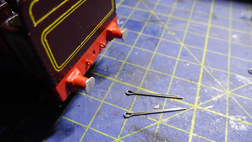
(Left: Vacuum pipes bent to shape produced by (W&T) Right: Additional chain holders made from Split pins)
Another small part that needed finishing and fitting was the loco's back-head using my normal methods which you can now see on You Tube, the back-head casting is primed, sprayed with Matt black, and the various pipes, brass, water glasses and regulator handle are picked out by hand, using a mix of Humbrol paint and Vallejo.
The small etched valve handles come from Mainly Trains (MT227). The back-head was test fitted to the model.

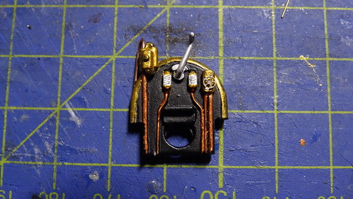
(Left: Painted in Matt black ready for detailing. Right: Detailed painted :Brass (70.801), Copper (70.999), Silver (70.997), White (34)
(Back-head test fitted to the loco body)
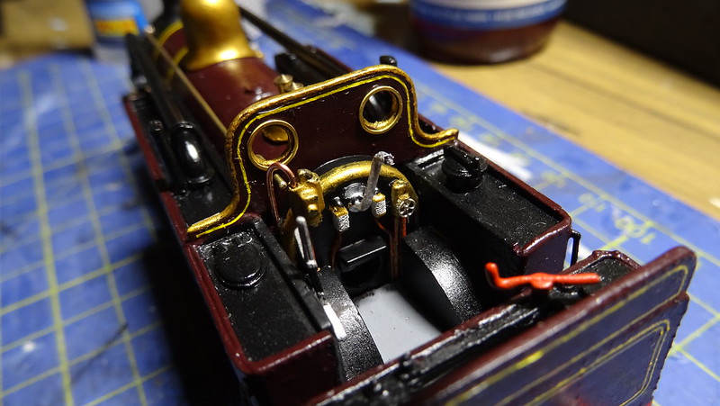
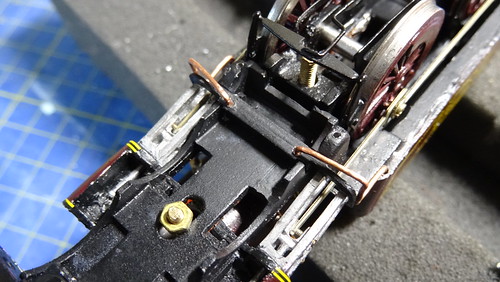
With the front bogie complete and fitted with a coupling my attention turned to the rear of the model and fitting a coupling to it. On drawings and on photos I could see what I believe is a vacuum cylinder mounted at the rear of the locomotive, so I managed to scratch build this from plastic rod and bits of brass strip and 0.8mm brass rod. The rod will go up from the brass strips which go around the cylinder to 2x holes drilled in the chassis. The middle section was lowered / filed down by 1.5mm to fit the coupling and to be at the correct height.

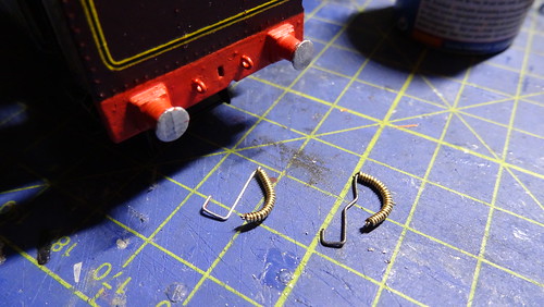
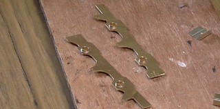
A couple of items missing from the rear are the guard irons, I have taken the decision not to put them on the front as there isn't enough room to put them in front of the bogie or even attached to the bogie. So I will be only putting them on the rear. The guard irons are fitted / mounted to the buffer beam, I have used some brass strip for these with the top section bent at 90 degree angle, 2x, 0.5mm holes were drilled to insert 2x brass rivets which were soldered in place, with the rivet still poking out the rear. 2X holes were drilled in the buffer beam for the mounting points for the guards, and the guards were then glued in place ready for painting.
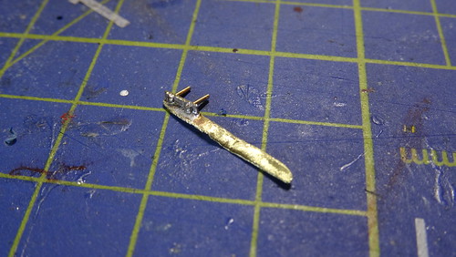
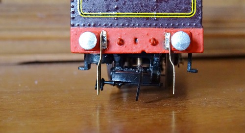
(Left: Buffer beam guard iron, Right: Guard irons fitted to the rear buffer beam, ready for painting)
These were bent in to shape using pliers and copying from images taken on my last visit to the London Transport Museum. Also added on the beams were the holders for the addition 2x chains either side of the main screw link couplings these additional chain holders were made from the good old split pins. A small hole drilled and the split pin cut down and glued in to position.
(Left: Vacuum pipes bent to shape produced by (W&T) Right: Additional chain holders made from Split pins)
Another small part that needed finishing and fitting was the loco's back-head using my normal methods which you can now see on You Tube, the back-head casting is primed, sprayed with Matt black, and the various pipes, brass, water glasses and regulator handle are picked out by hand, using a mix of Humbrol paint and Vallejo.
The small etched valve handles come from Mainly Trains (MT227). The back-head was test fitted to the model.
(Left: Painted in Matt black ready for detailing. Right: Detailed painted :Brass (70.801), Copper (70.999), Silver (70.997), White (34)
(Back-head test fitted to the loco body)
With the front bogie complete and fitted with a coupling my attention turned to the rear of the model and fitting a coupling to it. On drawings and on photos I could see what I believe is a vacuum cylinder mounted at the rear of the locomotive, so I managed to scratch build this from plastic rod and bits of brass strip and 0.8mm brass rod. The rod will go up from the brass strips which go around the cylinder to 2x holes drilled in the chassis. The middle section was lowered / filed down by 1.5mm to fit the coupling and to be at the correct height.
A couple of items missing from the rear are the guard irons, I have taken the decision not to put them on the front as there isn't enough room to put them in front of the bogie or even attached to the bogie. So I will be only putting them on the rear. The guard irons are fitted / mounted to the buffer beam, I have used some brass strip for these with the top section bent at 90 degree angle, 2x, 0.5mm holes were drilled to insert 2x brass rivets which were soldered in place, with the rivet still poking out the rear. 2X holes were drilled in the buffer beam for the mounting points for the guards, and the guards were then glued in place ready for painting.
(Left: Buffer beam guard iron, Right: Guard irons fitted to the rear buffer beam, ready for painting)
- Youtube/bluebellModelrailway
- https://railway-modeller-mw.weebly.com/
- VECTIS 3D: mademe.co.uk/shop/vectis-3d-models/
- https://railway-modeller-mw.weebly.com/
- VECTIS 3D: mademe.co.uk/shop/vectis-3d-models/
Re: BMR Workbench.
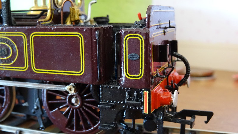
The buffer beam still requires some yellow + black lining similar to Maunsell coach lining around the outside of the beam, using fox transfers lining, again time consuming but will look good and will be worth it at the end.
Other small items made before lining was the pipe work and whistle in front of the cab.
Using some copper wire, a small handrail knob, and an old turned Tri-ang whistle to make up the assembly in front of the cab, 2x small holes were drilled in the V of the boiler casting and tanks to take the copper wire, the wire was soldered to the handrail knob, and old Tri-ang whistle was turned in a drill to try and get close to what is on the real thing, it was then soldered on to the top of the handrail knob, and then fitted.
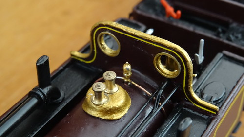

(Left: Whistle and pipe work fitted, Right: Lining added to buffer beams front and rear)
Me being me I wanted to add as much detail on as possible, which means destination boards and lamp irons, on the front buffer beam I used some think brass strip, soldering 2x sections of brass channel section on to the strip, also added was some square tube to replicate the lamp holders. The rear destination holders were glued to the rear of the bunker. The destination boards you will see a bit later on.

(Left: The destination and lamp bracket prior to gluing in place, Right: The brackets now glued in place)
More items added to the buffer beams were the now painted W&T vacuum pipes, these fit very tightly over the beam and only require a tiny amount of glue to stay attached. Also added was some lamp irons, now this loco has some slightly different ones so I had to settle with what I had available to me or looked similar, I found some on a Mainly Trains (MT187) etch for lamp irons.
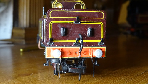
(Left :MT187 Lamp irons, GWR Parallel irons were used. Right: Glued in place on the rear, and one on top of the smoke-box)
Other small items made before lining was the pipe work and whistle in front of the cab.
Using some copper wire, a small handrail knob, and an old turned Tri-ang whistle to make up the assembly in front of the cab, 2x small holes were drilled in the V of the boiler casting and tanks to take the copper wire, the wire was soldered to the handrail knob, and old Tri-ang whistle was turned in a drill to try and get close to what is on the real thing, it was then soldered on to the top of the handrail knob, and then fitted.
(Left: Whistle and pipe work fitted, Right: Lining added to buffer beams front and rear)
Me being me I wanted to add as much detail on as possible, which means destination boards and lamp irons, on the front buffer beam I used some think brass strip, soldering 2x sections of brass channel section on to the strip, also added was some square tube to replicate the lamp holders. The rear destination holders were glued to the rear of the bunker. The destination boards you will see a bit later on.
(Left: The destination and lamp bracket prior to gluing in place, Right: The brackets now glued in place)
More items added to the buffer beams were the now painted W&T vacuum pipes, these fit very tightly over the beam and only require a tiny amount of glue to stay attached. Also added was some lamp irons, now this loco has some slightly different ones so I had to settle with what I had available to me or looked similar, I found some on a Mainly Trains (MT187) etch for lamp irons.
(Left :MT187 Lamp irons, GWR Parallel irons were used. Right: Glued in place on the rear, and one on top of the smoke-box)
- Youtube/bluebellModelrailway
- https://railway-modeller-mw.weebly.com/
- VECTIS 3D: mademe.co.uk/shop/vectis-3d-models/
- https://railway-modeller-mw.weebly.com/
- VECTIS 3D: mademe.co.uk/shop/vectis-3d-models/
Re: BMR Workbench.
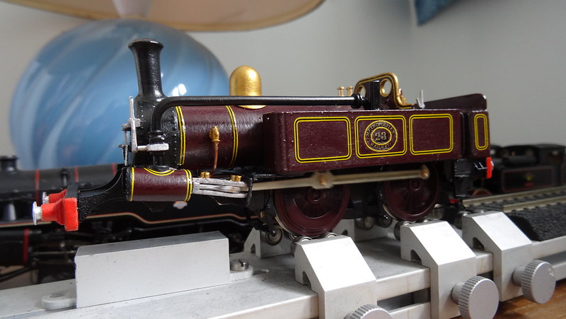
Another small addition again all detail is the numbers mounted to the chimney, now they may not be 100% correct or accurate but they will do, using some etched numbers which I usually use for SECR locos purchased from Roxey mouldings some time ago, were added to the chimney with a small amount of super glue gel applied using a cocktail stick, and look the part.
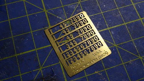
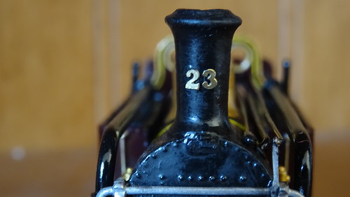
(Left: 7 inch SECR etched numbers from Roxey. Right: Numbers fitted to the Chimney)
Next came a bit more pipe work, using the copper wire 0.6mm diameter, to make the pipe running from the underside of the tank bending round and then under the running plate / motion bracket. 4x holes were drilled 2x on the underside of the tank one on each side and 2x on the underside of the motion bracket and glued in place.
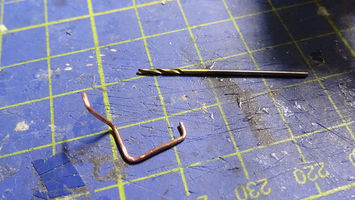
(Left: Copper wire bent to shape, 0.6mm drill bit. Right: Copper wire fitted to the model)
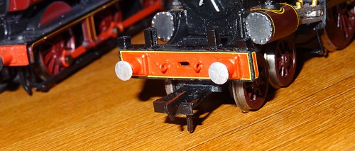
A few more items to go on, but that's after varnish, the model was spray with an Acrylic resin Satin varnish once fully dry the smoke-box was then brushed over with Matt Black (33) just to take the shine off the surface. The small items to be added to the buffer beam, screw link couplings and the 2 additional chains either side of the main coupling which attach to the cotter/split pins which were featured earlier on. The chains purchased from a well known auction site, 2mm fine chain blackened mainly used for jewellery like the copper wire.
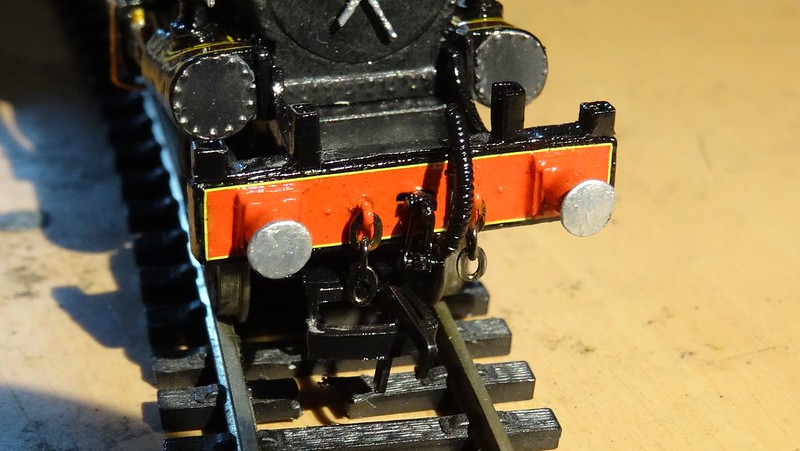
(Additional chains added either side of the screw link coupling)
(Left: 7 inch SECR etched numbers from Roxey. Right: Numbers fitted to the Chimney)
Next came a bit more pipe work, using the copper wire 0.6mm diameter, to make the pipe running from the underside of the tank bending round and then under the running plate / motion bracket. 4x holes were drilled 2x on the underside of the tank one on each side and 2x on the underside of the motion bracket and glued in place.
(Left: Copper wire bent to shape, 0.6mm drill bit. Right: Copper wire fitted to the model)
A few more items to go on, but that's after varnish, the model was spray with an Acrylic resin Satin varnish once fully dry the smoke-box was then brushed over with Matt Black (33) just to take the shine off the surface. The small items to be added to the buffer beam, screw link couplings and the 2 additional chains either side of the main coupling which attach to the cotter/split pins which were featured earlier on. The chains purchased from a well known auction site, 2mm fine chain blackened mainly used for jewellery like the copper wire.
(Additional chains added either side of the screw link coupling)
Last edited by mattmay05 on Sat May 28, 2016 9:19 pm, edited 1 time in total.
- Youtube/bluebellModelrailway
- https://railway-modeller-mw.weebly.com/
- VECTIS 3D: mademe.co.uk/shop/vectis-3d-models/
- https://railway-modeller-mw.weebly.com/
- VECTIS 3D: mademe.co.uk/shop/vectis-3d-models/
Re: BMR Workbench.
- A new chassis -
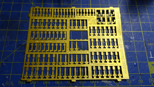
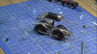
I took some time to review the chassis, although running, it still wasn’t running that well, the chassis was set up with a jig to ensure it was square, straight and level, and checked on a flat surface like mirror glass for example. Yet I still had some issue with the chassis being straight, either a mounting position was out, or an axle hole was out of position. No matter what I tried it still wasn’t right, despite improving it slightly the chassis was still rocking, with only 3 wheel flanges touching the surface.
I took the decision to bin the chassis... fortunately thanks to a member on RMweb, pointed me in the direction of Alan Gibson workshop, who produce milled chassis frames, they do a Metropolitan A-Class but it’s not known if it will fit an old K’s kit, spacers, frames, and connecting rods were ordered late March.
The frames and spacers arrived a week or so later, and after a few checks and measurements the Alan Gibson frames would fit with some adjustments and shortening as the frames spanned the full length of the loco.
Some parts I made for the original chassis were transplanted on to the new chassis which went quite well.
The new chassis is square level and runs beautifully, in addition to the new chassis I also purchased some new connection rods from Alan Gibson to replace the rather thick and had it etched rods from the K's Kit.
There is a video on the building of the chassis which is available on my Workbench playlist on YouTube helping to pass on skills to new modellers:
https://youtu.be/f1K-O09LIJU
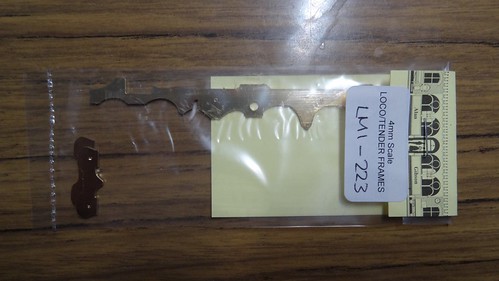
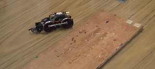
(Alan Gibson's chassis taking shape, to replace the K's original which had problems, possibly incorrect position of chassis screw fixings)
This is part is really just a bit of fun really, I wanted to make some destination boards which were fitted in to slots on the front buffer beam, and the rear of the bunker. I managed to get hold of a document which had the destinations written in the correct Font which correct backing colour, these were then put on to a photo editing software to adjust the size to fit the brass plates. These destinations were printed out on to transfer paper, and fitted to the brass.
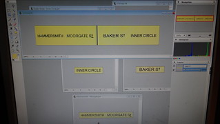
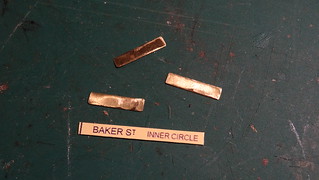
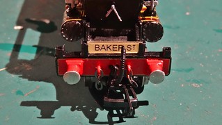
(Destination boards being produced for the A-Class held in brackets on the buffer beam and bunker)
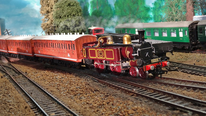
So with all the work on the chassis now complete and running nicely, and all the details done for this model, there is only one thing to do. Fit a crew add a bit of coal, and couple it up to some coaches. But before then I had an item arrive for it which I completely forgot about, ordered from Narrow Planet a pair of builders plates which are on either side of the bunker, just painted black which no highlights on the lettering.
More Soon.
I took some time to review the chassis, although running, it still wasn’t running that well, the chassis was set up with a jig to ensure it was square, straight and level, and checked on a flat surface like mirror glass for example. Yet I still had some issue with the chassis being straight, either a mounting position was out, or an axle hole was out of position. No matter what I tried it still wasn’t right, despite improving it slightly the chassis was still rocking, with only 3 wheel flanges touching the surface.
I took the decision to bin the chassis... fortunately thanks to a member on RMweb, pointed me in the direction of Alan Gibson workshop, who produce milled chassis frames, they do a Metropolitan A-Class but it’s not known if it will fit an old K’s kit, spacers, frames, and connecting rods were ordered late March.
The frames and spacers arrived a week or so later, and after a few checks and measurements the Alan Gibson frames would fit with some adjustments and shortening as the frames spanned the full length of the loco.
Some parts I made for the original chassis were transplanted on to the new chassis which went quite well.
The new chassis is square level and runs beautifully, in addition to the new chassis I also purchased some new connection rods from Alan Gibson to replace the rather thick and had it etched rods from the K's Kit.
There is a video on the building of the chassis which is available on my Workbench playlist on YouTube helping to pass on skills to new modellers:
https://youtu.be/f1K-O09LIJU
(Alan Gibson's chassis taking shape, to replace the K's original which had problems, possibly incorrect position of chassis screw fixings)
This is part is really just a bit of fun really, I wanted to make some destination boards which were fitted in to slots on the front buffer beam, and the rear of the bunker. I managed to get hold of a document which had the destinations written in the correct Font which correct backing colour, these were then put on to a photo editing software to adjust the size to fit the brass plates. These destinations were printed out on to transfer paper, and fitted to the brass.
(Destination boards being produced for the A-Class held in brackets on the buffer beam and bunker)
So with all the work on the chassis now complete and running nicely, and all the details done for this model, there is only one thing to do. Fit a crew add a bit of coal, and couple it up to some coaches. But before then I had an item arrive for it which I completely forgot about, ordered from Narrow Planet a pair of builders plates which are on either side of the bunker, just painted black which no highlights on the lettering.
More Soon.
- Youtube/bluebellModelrailway
- https://railway-modeller-mw.weebly.com/
- VECTIS 3D: mademe.co.uk/shop/vectis-3d-models/
- https://railway-modeller-mw.weebly.com/
- VECTIS 3D: mademe.co.uk/shop/vectis-3d-models/

Re: BMR Workbench.
impressive stuff as always! the numbers on the chimney work well
Re: BMR Workbench.
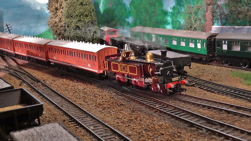
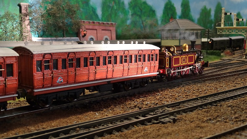
And now back on the mainland some completed images, PDF will be on the website shortly.
- Youtube/bluebellModelrailway
- https://railway-modeller-mw.weebly.com/
- VECTIS 3D: mademe.co.uk/shop/vectis-3d-models/
- https://railway-modeller-mw.weebly.com/
- VECTIS 3D: mademe.co.uk/shop/vectis-3d-models/
Re: BMR Workbench.
That's a real work of art! So beautiful to look at.
Re: BMR Workbench.
Many thanks Gary.
- Youtube/bluebellModelrailway
- https://railway-modeller-mw.weebly.com/
- VECTIS 3D: mademe.co.uk/shop/vectis-3d-models/
- https://railway-modeller-mw.weebly.com/
- VECTIS 3D: mademe.co.uk/shop/vectis-3d-models/
Re: BMR Workbench.
I've written up another small conversion, a re-name, re-number, and a modification to the tender.
This one was a Merchant Navy, purchased as Clan Line with the 6,000 tender, my intention was to rename it to Port Line, Renumber to 35037, and try and get the tender the same as what it last ran with which is a 5,000 gallon Series type (one Hornby do not produce).
Follow the Link to read more:
https://drive.google.com/file/d/0B_s...d1WVZQa2c/view
- Youtube/bluebellModelrailway
- https://railway-modeller-mw.weebly.com/
- VECTIS 3D: mademe.co.uk/shop/vectis-3d-models/
- https://railway-modeller-mw.weebly.com/
- VECTIS 3D: mademe.co.uk/shop/vectis-3d-models/
Re: BMR Workbench.
I've completed another of my own personal projects, I purchased a Bachmann A1 model from a well known auction site for £30, which someone tried to convert in to Tornado, sadly it was covered in superglue and a few details were not quite right.
After a lot of work cleaning, and tidying up and also finding replacement parts, I have finally completed the glued mess in to something half decent.


After a lot of work cleaning, and tidying up and also finding replacement parts, I have finally completed the glued mess in to something half decent.
- Youtube/bluebellModelrailway
- https://railway-modeller-mw.weebly.com/
- VECTIS 3D: mademe.co.uk/shop/vectis-3d-models/
- https://railway-modeller-mw.weebly.com/
- VECTIS 3D: mademe.co.uk/shop/vectis-3d-models/
-
Bufferstop

- Posts: 13821
- Joined: Thu Mar 11, 2010 12:06 pm
- Location: Bottom end of N. Warks line
Re: BMR Workbench.
Another excellent project completed. We are running out of superlatives to match your output  Great!
Growing old, can't avoid it. Growing up, forget it!
My Layout, My Workbench Blog and My Opinions
My Layout, My Workbench Blog and My Opinions