How to: Control Panel

Enter this forum if you wish to help the growth of New Railway Modellers.
Hulldude15
Posts: 202
Joined: Wed Aug 19, 2009 5:19 pm

How to: Control Panel

Post by Hulldude15 »

Hi,

This guide will teach you how to make a control panel, like the one on my layout. Before I begin, I must add that even though it works, the way I have done it may not be the best way of doing it and there are other ways. If you have any comments or questions, feel free to say.

You will need:

Point Motors - However many you need, I used Hornby Surface mounted point motors as they are easy to fit and reasonably cheap.
Switches – Make sure they spring back to the centre, so you will need a (on)off(on) SPDT switch. Other types of switches can be used but this is my method remember! They can be obtained here: http://www.newmodellersshop.co.uk/elect ... itches.htm Again, as many as you need but remember 1 switch can control 2 points if you need it to, say if you have a crossover.
A panel to mount your switches on, explained below.
A CDU – Capacitor Discharge Unit – Can be obtained from eBay. This stops your points burning out if you keep the switch held down and also helps fire a big burst of power if you are switching more than one point.
Green, Red and Black Wire, the amount depends on the size of your layout and where your panel is in relation to the points. I have used 24/0.2 equipment wire
A power supply, mine gives an output of 16vDC, but most CDU’s will take an input of 16 to 24 volts.
A soldering iron + solder
Choc Blocks (Connector Blocks) - I used the 5A version. Again available from NRM shop.
A small slotted head screwdriver.
Wire Strippers
Soldering Iron + Solder


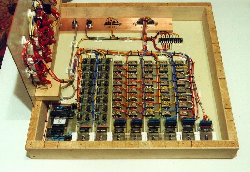
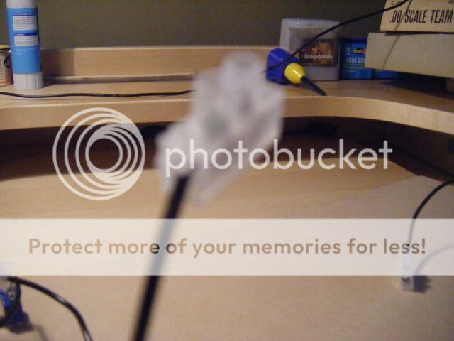
First of all, you are going to need a board/box to have your track plan and switches on. For this I engraved my track plan onto a piece of 4mm MDF using a laser cutter. Most people won’t have access to a laser cutter, but other alternatives are available, e.g. simple boxes, which can be bought from Maplin, or you could make your own. You could draw your track plan or use tape or print it onto card and stick it on; at this stage you can do whatever! The images below show my control panel before the sides have been taken off.
ImageImage
Next, you will need to drill your holes, as shown above. My switches needed 6mm holes, do a test drill outside of your plan just to check your switches fit it ok.
Your switches will then need to be screwed in, make sure you turn the underside of the switch round, so you have the switch flicking up and down or left and right or whatever you like. I liked to number my switches and points, which created an order to in which to precede e.g. Points 1 will be installed, then 2 and 3 etc. Or Switch 1 will be soldered then 2 and 3 etc.
Image ImageImage
Image
It will start looking like a control panel now, but next comes the soldering! When I started my control panel, I was dreadful at soldering, but after a few switches I was perfect! (Well almost!) The trick for me is to make sure the iron is very hot, and then place on the connection you’re soldering for a few seconds, offer the solder to the iron close to the joint and let it flow into it.
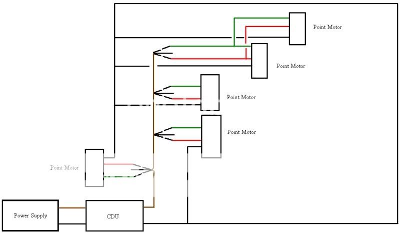
Here’s a wiring diagram that I used to help me, please note that I have more point motors and it just shows me how to do a few and that the switch at the top controls two points.
Image

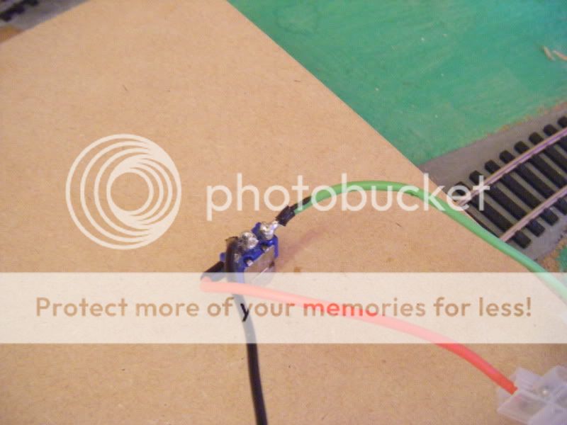
As my shed is at the bottom of my garden, I wanted to do all the soldering in my nice warm room and take it down when I was ready to attach the wires to the points, so I soldered 10cm pieces of wire to the switches in my house, so I could take it down to my shed and just connect it all up. (Alternatively you could solder the wires that will go directly to the point motor, so there is no need to do this) Solder the Green and Red wires to the outer solder lugs and solder black for the inside lug. Here’s one of my better ones when I started:
ImageImageImage

Ok, so you have soldered your first few wires or maybe all of them if you were quick. What’s next? Well you need to attach chocolate blocks to the ends of all the wires. IMPORTANT: If you are using the alternate method described above, you still need to attach choc blocks, but the ends of the black wires only, not green and red.
Image
Image

Next you need all the ends of the black wires to connect to the input. As it would not be possible to shove all the black wire ends into the CDU output, it is done by having a wire leading from your CDU to the choc block on the end of the wire on your first switch, a wire leading from your first switch to your second, another wire then from your second to your third, therefore you have two wires leading out of each choc block, except your last switch. (You could add your CDU now but make sure you get the first wire to be in the right output (DC-), read your CDU’s instructions and this will be shown later.) Here are some pics explaining this: Note: I hadn’t got round to soldering the green and red wires yet in these pics.
ImageImage
ImageImage

Now you have done all the soldering that you need to do, it’s time to install all your point motors if you haven’t already done so. I won’t explain how to fit a point motor as you should have instructions supplied. Hopefully, your point motor has 3 wires coming out from it: Green, Red and Black.

Once you have done all this, you are ready to connect it all up. Start with you first switch and point. Connect the red wire from your switch (or the 10cm wire with choc block) to the red wire coming from the point motor, using... You guessed it... Red wire! Repeat with the steps with Green Wire. BUT with the black wire coming from your POINT MOTOR needs to go back to the CDU, not the switch. Once again it would be silly to try and shove all the black wire into the CDU, so do a similar process to the black wires earlier. Have one wire from the CDU output (DC+)leading to two wires, one to the point and the other a short wire leading to the next two connections and so on.
Image
Image
You can either keep going with the rest of the wiring now or you can give your first wired up point motor a test. Before you can, take your power supply and cut of the end that doesn’t go into the wall, revealing two wires a positive and a negative. Strip half a centimetre of the plastic of each wire, and place into the CDU like shown, with the white wire on the right of the AC inputs and the other in the left AC input. As I said earlier, for the outputs: (DC-) for the wire going to the switch, and (DC+) for the wire to the point motor.
Image
Image

Hopefully it will work and look something like this:
Image
ImageImage

If it is not working, try this:

Are your inputs and outputs of your CDU correct?
Are your connections correct and secure?
Is the power on!?
Has any of the fine wiring of the point motor snapped? (this has happened to me)
Is there a short circuit?
Does any of your soldering or bare wires on your switch touch each other?

Sometimes, my points occasionally stop, but this is usually because a wire might have been accidently tugged causing a bad connection, so undo the offending connection and redo it.

Hope you understand this and nothing has been left out. Feel free to ask any questions...

Hulldude15

Visit my layout at: http://www.newrailwaymodellers.co.uk/Fo ... 90#p367218
m8internet
Posts: 1640
Joined: Mon May 15, 2006 7:32 pm
Location: Cumbernauld, Scotland

Re: How to: Control Panel

Post by m8internet »

That is an awful lot of terminal blocks
Why not keep them together in sets of three, thus keeping the wires together
Glasgow Queen Street Model Railway layout : modern image N gauge using DCC
sishades
Posts: 1006
Joined: Sat Feb 24, 2007 8:08 pm
Location: Burston Norfolk

Re: How to: Control Panel

Post by sishades »

Good article. Instead of having choc blocks you could have a "black wire bus". Then connect the switches to the bus uising blue wire connectors.
High towards the far post,Howard with a header,Hes done it!Steve Howard has scored for Leicester City,Bedlam here at the Walkers Stadium. the Leeds United players are flat out on the turf in utter despair. Leicester City are going to win again
Hulldude15
Posts: 202
Joined: Wed Aug 19, 2009 5:19 pm

Re: How to: Control Panel

Post by Hulldude15 »

sishades wrote:Good article. Instead of having choc blocks you could have a "black wire bus". Then connect the switches to the bus uising blue wire connectors.
m8internet wrote:That is an awful lot of terminal blocks
Why not keep them together in sets of three, thus keeping the wires together
Well as I said, this was my of doing it, if you want to do it with less terminal blocks, so be it! :D I understand what you say and you're most likely correct, but for a newbie that's what I did.
User avatar
SouthernBoy
Posts: 1753
Joined: Sun Oct 08, 2006 11:01 pm
Location: The past: We do things differently there

Re: How to: Control Panel

Post by SouthernBoy »

I think that's really helpful.

Like you say, there are variations on the basics, but if I was starting out now I'd have found something like that really useful.

Hopefully others will add more good information over time.
b308
Posts: 5106
Joined: Sat Apr 15, 2006 5:48 pm
Location: North Worcs

Re: How to: Control Panel

Post by b308 »

Mine have been very similar, but like the others I don't use terminal blocks if there are more than three wires to the panel, I tend to use old computer plugs/sockets (if large number of wires), or audio ones from Maplins for smaller numbers. Also I've seen several panels using perspex for the top with the trackplan painted on or using lining tape. TBH I prefer perspex (clear or painted) to wood for that purpose... but as you say its personal preference!
User avatar
bike2steam
Posts: 1050
Joined: Wed Jan 13, 2010 2:46 pm
Location: near Blandford

Re: How to: Control Panel

Post by bike2steam »

I always use engraving laminate plastic tops to my control panels, engraved by a friend who has a machine to do it, and will also do it for anyone else who asks.
My wiring system is;-
switch - solder tag - 'D' connector, one side set in side of control panel - loom - 'D' connector, one side set in side of baseboard - solder tag - track/accessory. All my layouts are built to be portable for showing.
terminalblocks
Posts: 3
Joined: Fri Feb 11, 2011 1:33 am
Contact:

Re: How to: Control Panel

Post by terminalblocks »

b308 wrote:Mine have been very similar, but like the others I don't use terminal blocks if there are more than three wires to the panel, I tend to use old computer plugs/sockets (if large number of wires), or audio ones from Maplins for smaller numbers. Also I've seen several panels using perspex for the top with the trackplan painted on or using lining tape. TBH I prefer perspex (clear or painted) to wood for that purpose... but as you say its personal preference!
you should really consider using terminal blocks, ESPECIALLY when there are more than three wires. but yes, personal preference is important as well.
b308
Posts: 5106
Joined: Sat Apr 15, 2006 5:48 pm
Location: North Worcs

Re: How to: Control Panel

Post by b308 »

terminalblocks wrote:you should really consider using terminal blocks, ESPECIALLY when there are more than three wires.
Why?

My layouts are exhibition layouts where they are assembled and dismantled, as such a "plug" is far more convenient than a terminal block and easier to use. On a control panel as in the earlier post, I'd have thought that a multi connector is a much better and neater solution, I'm assuming that he's used terminal blocks to make the panel removable, if thats not the case and its permanent then soldered joints are better than blocks or connectors!
User avatar
Dale_the_noob
Posts: 328
Joined: Thu Apr 03, 2008 7:07 pm
Location: Berkshire

Re: How to: Control Panel

Post by Dale_the_noob »

terminalblocks wrote:
b308 wrote:Mine have been very similar, but like the others I don't use terminal blocks if there are more than three wires to the panel, I tend to use old computer plugs/sockets (if large number of wires), or audio ones from Maplins for smaller numbers. Also I've seen several panels using perspex for the top with the trackplan painted on or using lining tape. TBH I prefer perspex (clear or painted) to wood for that purpose... but as you say its personal preference!
you should really consider using terminal blocks, ESPECIALLY when there are more than three wires. but yes, personal preference is important as well.
If its a do once thing, then solder

If its something you need to disconnect frequently, use a variety of connectors depending on your current. This will allow quick release and will be simpler to do with less chance of error.
User avatar
bike2steam
Posts: 1050
Joined: Wed Jan 13, 2010 2:46 pm
Location: near Blandford

Re: How to: Control Panel

Post by bike2steam »

A few pics of the control panel on my latest layout, note very few connector blocks :) .
Attachments
pauls layout 010.JPG
pauls layout 010.JPG (140.05 KiB) Viewed 8166 times
pauls layout 009.JPG
pauls layout 009.JPG (136.04 KiB) Viewed 8168 times
pauls layout 007.JPG
pauls layout 007.JPG (124.86 KiB) Viewed 8166 times
Gordon H
Posts: 214
Joined: Tue Mar 14, 2006 1:08 pm
Location: UK
Contact:

Re: How to: Control Panel

Post by Gordon H »

Planning in advance is key to producing a good, reliable and maintainable Control Panel. The problem with the 3D 'rats nest' wiring approach is that although it might appear to make wire tracing a bit easier for fault finding, you run the risk of causing further damage by rummaging around amongst it all whilst doing so. Far better to plan out where the wires have to go beforehand on a wiring list, including where multiple commoned ends have to join. Then you can put in facilities to deal with such cases, such as commoning tag strips.
Screw terminal blocks have their place in the overall scheme of things, but for me, mid-air wiring is not one of them :wink:
If you must use them, avoid the urge to tin the ends of your exposed wires, other than perhaps just sufficient to stop the strands splaying. Screw terminals are intended to deform wire strands as they are tightened, and tinning the entire end prevents this from happening properly, making for a brittle joint.

Here is one I prepared earlier (about 15 years ago - frightening thought :shock: ). And not a terminal block in sight!
It is perhaps more complicated than the average panel because it includes both manual controls and computer interfacing circuitry.

Image
b308
Posts: 5106
Joined: Sat Apr 15, 2006 5:48 pm
Location: North Worcs

Re: How to: Control Panel

Post by b308 »

Some impressive panels there... Makes my cheapo efforts look poor in comparison!

Well done, folks!
bocaj
Posts: 680
Joined: Mon Mar 07, 2011 6:58 pm
Location: Leeds
Contact:

Re: How to: Control Panel

Post by bocaj »

Hi,
That looks impresseive,
I will not be needing one of these as my points are going to DCC controlled
georgehgv
Posts: 159
Joined: Tue Oct 30, 2012 8:14 am

Re: How to: Control Panel

Post by georgehgv »

m8internet wrote:That is an awful lot of terminal blocks
Why not keep them together in sets of three, thus keeping the wires together
Definitely keep them in blocks, numbered in pairs and use a common bus for the blacks.

BTW I used crimps with small spade instead of soldering to the points, works great too.

Well done with the panel layout though. Geo
Enjoying the ride playing trains like never before. Building a model railway but not too specialised.
Post Reply