This I believe is a product that will interest most so I have broken it up into 3 stages. Basic install, advanced install and technical information. If possible can we keep it focused on the kit, thanks.
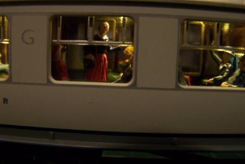
For most of us, lighting in coaches adds that extra realism, if done properly. It adds that extra detail and gives your coaches another dimension. Further to that, you can then detail your interiors, add passengers and it almost comes alive.
Jubilee coach with Flicker Free added.
DCC Concepts have developed a kit to suit just about any coach on AC DC or DCC called Flicker Free.
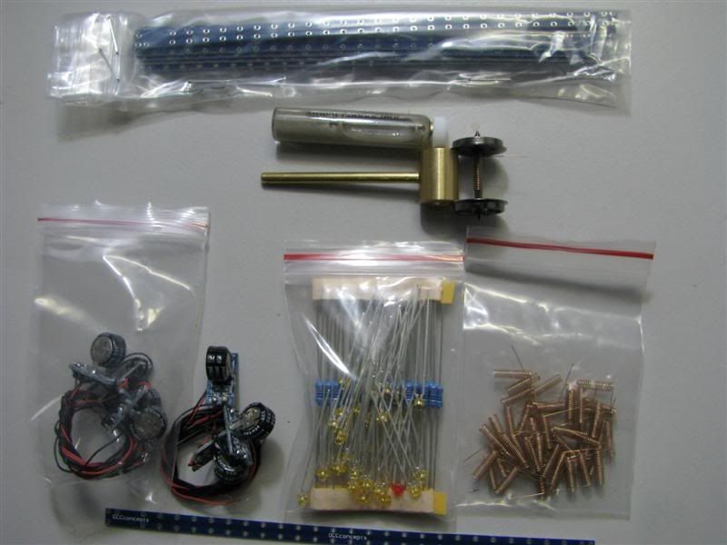
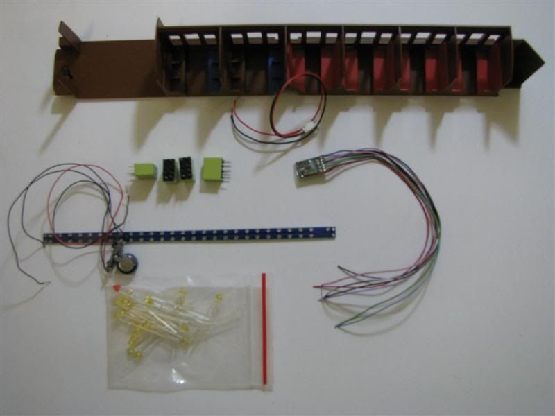
The kit consists of the following:
30 Prototype or golden white LEDs
3 Red LEDs
33 x 1k ohm resistors
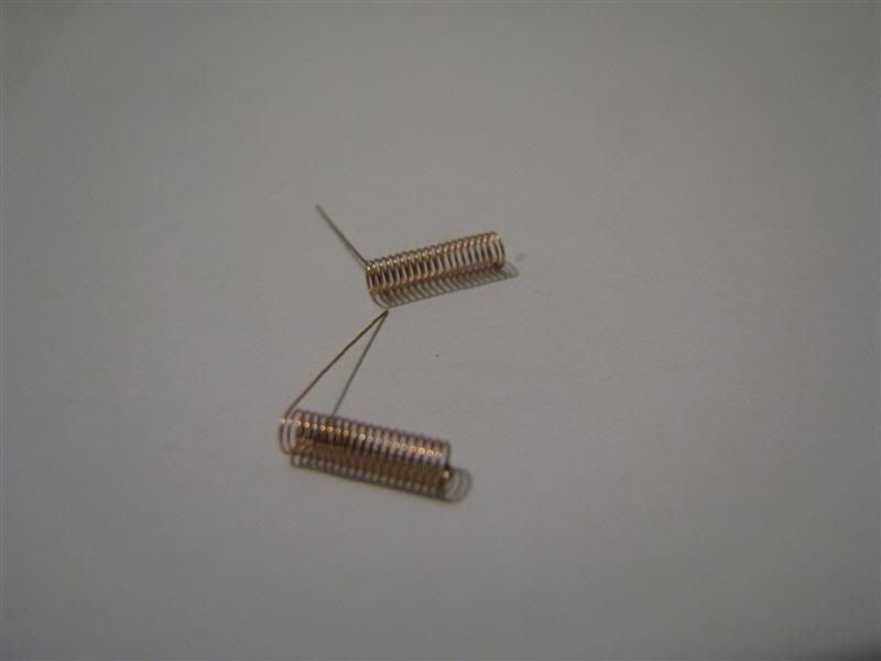
12 pick up springs
6 150mm mounting boards.
6 Flicker free units with full instructions. This looks like a simple device but includes super capacitors, rectifiers, voltage control and carefully controlled current limiting on a tiny PCB. It is very efficient at what it does.
The Flicker Free kit
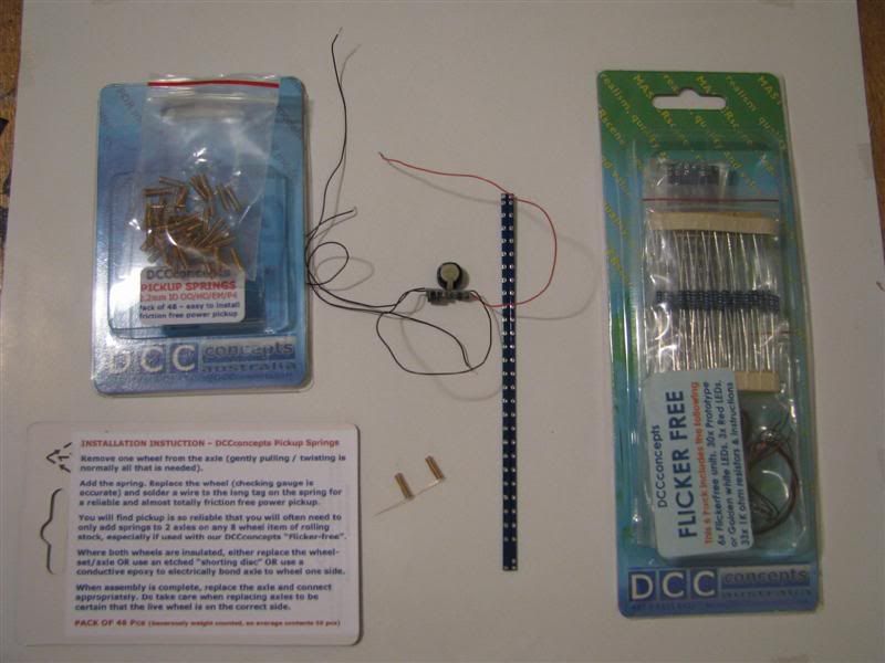
Kit plus back to back gauge and conductive paint.
Close up of the coach pickup's
It is available from the following suppliers:
Broomsgrove models
http://www.bromsgrovemodels.co.uk/
Direct link to Broomsgrove models Flicker Free
http://www.bromsgrovemodels.co.uk/pi109 ... egoryId=29
DCC Supplies
http://www.dccsupplies.com
DCC Concepts
hppt://www.dccconcepts.com
Flicker Free has a I year "Goof Proof" warranty.
Before we start let me pass on a couple of tips I found out the hard way!
1. Always if possible remove the couplings. The tension locks always get in the way.
2. With any of the newly manufactured highly detailed coaches they have very small parts, easily broken. Remove what you can and be very careful.
3. Invest in a back to back wheel gauge, also manufactured by DCC Concepts. It comes in a range of sizes to suit EM 00 HO etc. It will sort 80-90% of your de-railing problems and makes a handy wheel holder when soldering. Solved so many problems on loco's too.
4. Take your time and study the coach you plan to convert. I was caught on this big time. I set up a mini production line with 9 of the new Hornby "Blood and Custard" coaches. The coach chassis all looked the same, sadly they were not until I had just about finished when I realized steps were not aligned with doors. I am only talking 2-3mm out. So mark them brake end, 1st 3rd etc.
5. If you are a beginner consider drawing a small wiring diagram, it really helps you get it right in your head. If your still unsure ask on here, everybody is more than happy to help.
6. If you are unsure with wire lengths cut them long, easier to trim than add to.
7. May sound silly, wash your hands every 1/2 hour, and try not to touch the clear plastic on the inside.
After you have identified how to get into your coach remove the body from the chassis. Usually with a Hornby coach for example they have 4 de-tens, 2 at each end that you press. I find if you lightly push on a buffer while pressing the de-ten it pops out. There will also be 2 located in the centre of the coach. Best method here is sliding a business card from one end to release it.
So you are in, remove the interior remembering orientation and how it fitted. We now have 3 basic parts the outer coach body, interior and chassis.
Decide where you are going to put the flicker free unit. In a brake coach, the brake compartment, or in a toilet, it will fit (it fits N, so OO is dead easy). Remove the coach wheel set closest to that location and carefully remove the wheels.
If you have wheels that are plastic the need to be replaced and must have ideally 1 side insulated. Hornby's B+C coaches have both sides insulated so that is where the conductive paint is used.
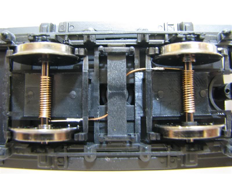
Remove 1 wheel from the axle and put a pick up on.
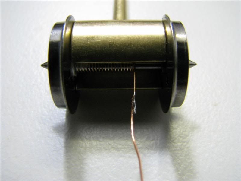
As you can see I have put the pickup on and added the conductive paint which is good for about 120mA, located on the left hand side. Got to say this style of pickup has a very low co-efficient of friction. It really works well and in use it adds no drag to the coach at all! That’s a fact. I have also soldered my wire on. Due to the very tight tolerances in this coach I decided to go with 0.25mm enamel wire. A spool cost me $6.00 at my local electronic shop.
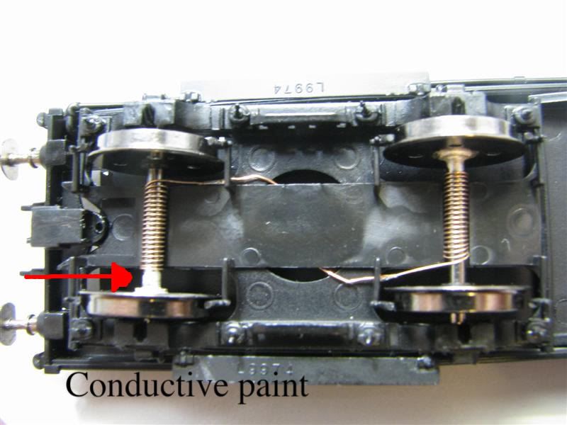
Back in the chassis and now you can clearly see the conductive paint. The wire is no way visible from the side.
Now for the interesting part. OK firstly a little on LED's and the boards. The LED's used are called prototype white and are custom manufactured for DCC Concepts only. These LED's are the ones for the steam era and early diesel.
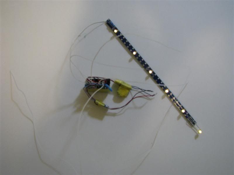
We need to identify the positive and negative legs of the LED. The positive is always the longest leg and the second method I use is the positive side of the LED is curved. The board is 5mm wide with 5mm spacings and you can solder on both sides. It has a special location for the resistor and the opposite end has 2 holes if you need to link another board.
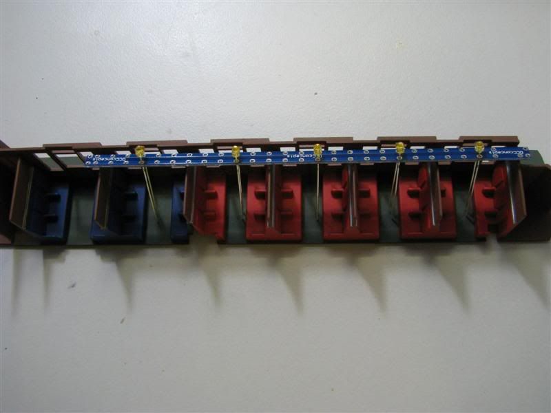
I find the best way is to place the board in the interior and put each LED in so we have the correct spacing.
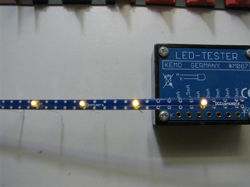
Once your happy and before you solder your LED's in check that they work and your polarities are correct by conducting a simple operational test. Does it work!
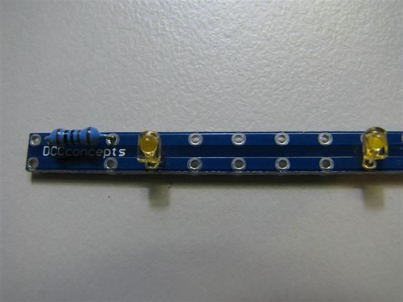
DCC Concepts have made the next part real easy for us. Once you are happy with placement of LED's everything is working, time to solder them in. Just apply a small amount of solder and make sure you got a good joint. 2-3 seconds should do it. Try not to go over that or you may damage the LED.
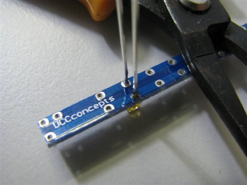
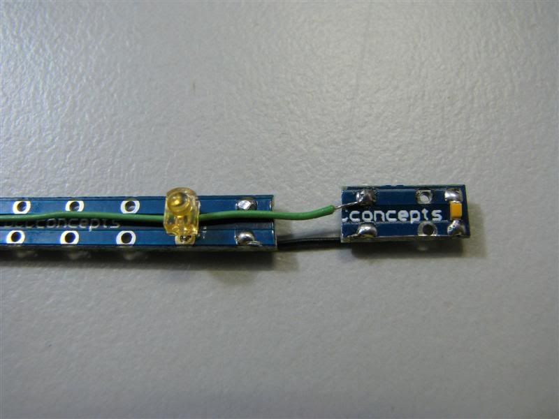
Add your 1k or 1000 ohm resistor. Now you might want to add more resistance to reduce the light to suit your era. That's your call. Notice the curved end of the LED this as I said identifies positive and this is the leg that should have the resistor in series with it. You cannot see it but their is a break in the circuit between the 2 mounting points for the resistor.
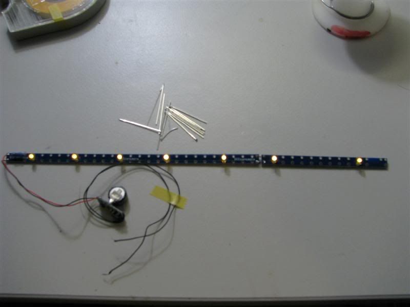
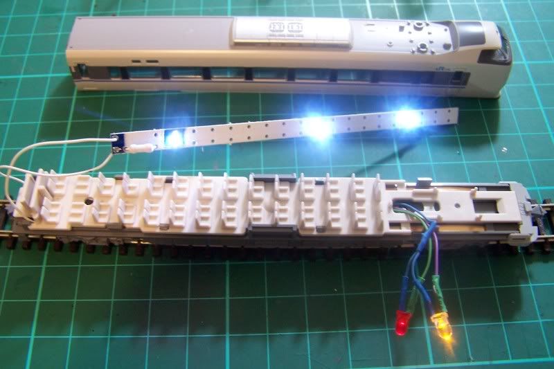
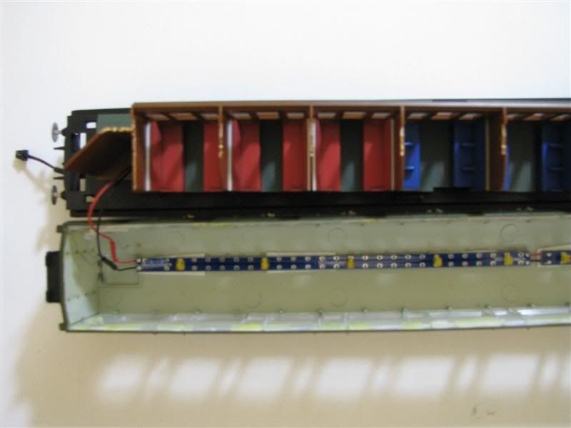
The last part is to add the heart of the system the "Flicker Free" unit. Red (+) and black (-) got to board, both black wires to your pickup's. Remember if you have AC or DCC the voltage has passed through the flicker free unit and is now DC. Dont wire it backwards! Simple and straight forward. See all the legs I have cut off, keep them great for adding glue, links etc.
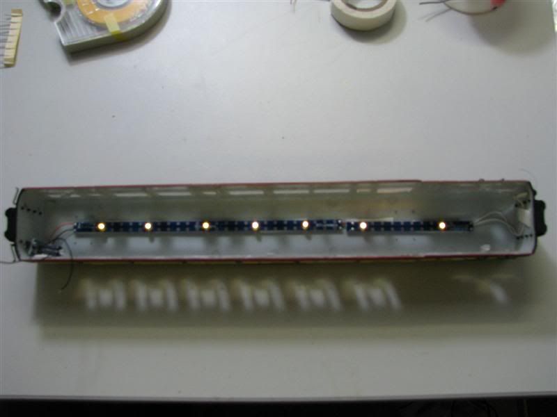
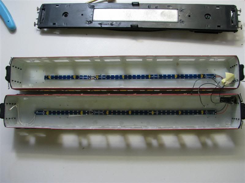
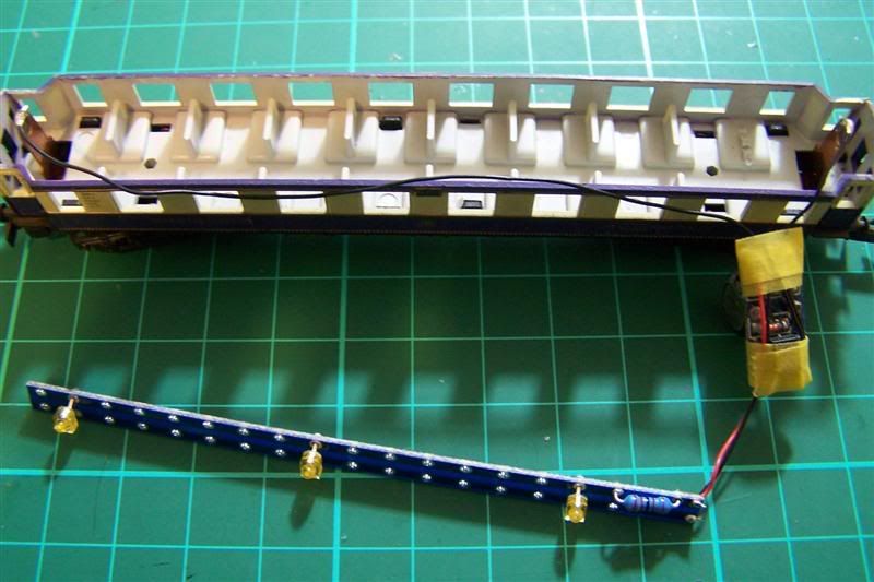
Nearly there, using the double sided sticky tape supplied in the kit we can place in the coach remembering which end has the coach pickup's. I used to paint the boards the same colour as the roof, no point unless your layout is 6ft above you. Guys you just don't see it, unless you go looking for it. Add passengers if you want, I like to in some cases.
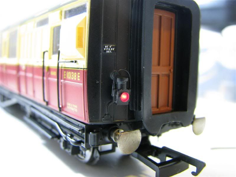
1 brake 1 standard coach side by side. I have run a brake light but in series on the positive leg I have put a 30k resistor on top of the 1 k for the red LED only. That is on the white wiring.
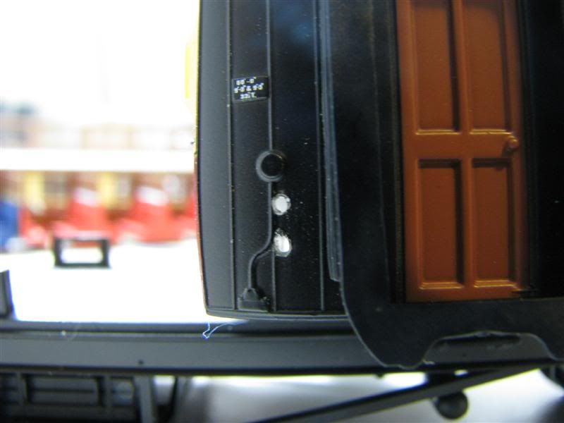
2 0.6mm holes drilled for tail light on brake coach. Best method I found was to drill the first hole. Put the longer leg in and see where it marks the body. This is the location for second hole.
As you can see on this coach the board is painted. In this case I did need to along with the Flicker Free unit. At the end their is a SMD LED ideal for n gauge and very tight applications. You will need to run a separate resistor as this will cause volt drop if put in parallel with the other prototypical white. The red LED is also a little thief so watch him also.
SMD LED in prototypical white. Very good for those hard or tight spots. Mind you I lose more than I solder on. Slippery little suckers!
Last part, drill a hole 2mm for the exit point of your wire. This way it doesn't get caught in everything. Solder your 2 ends to the enamel wire don't forget some heat shrink leaving enough if you ever want to get back into the coach. Take your time and put it back together remembering correct orientation alignment of doors with footplates.
Don't be like me and think because you have done a few you know it all. Set up a mini production line and find you got to pull them all apart to fix the problem.
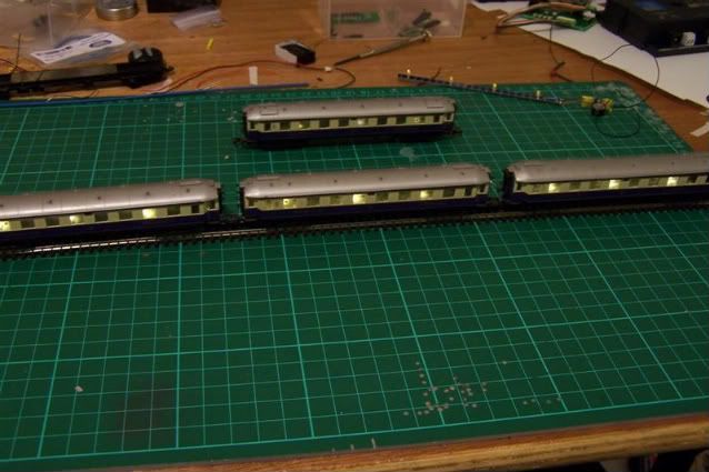
The results.
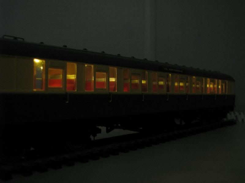
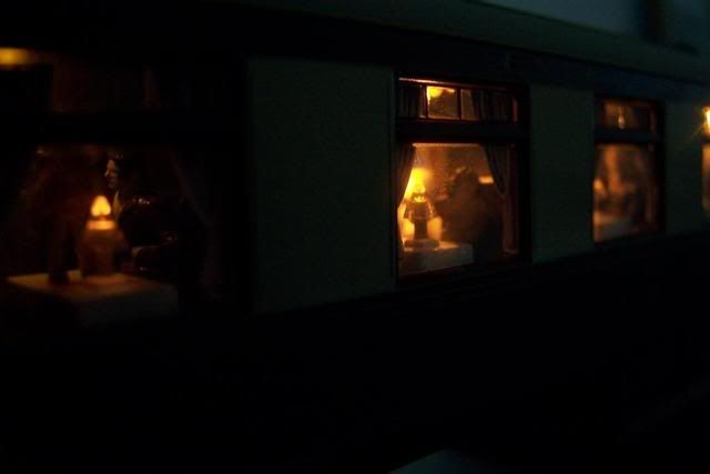
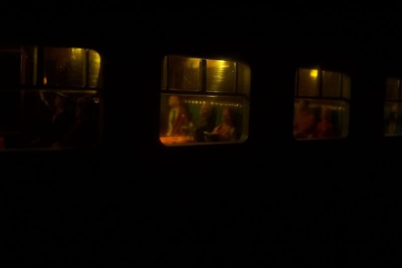
Hornby Pullman with flicker free and extra lighting added, table lamps just didn't cut it.
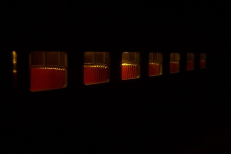
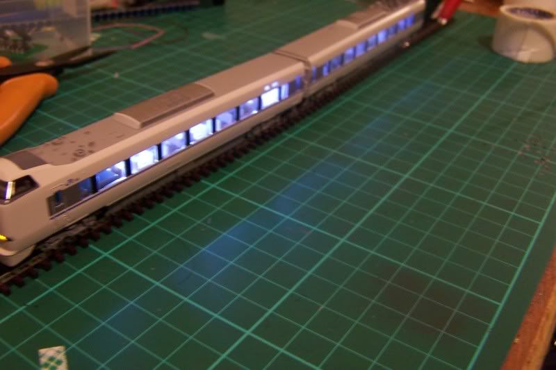
I think this really shows how flicker free works. See no tracks, so no voltage, lights still on.
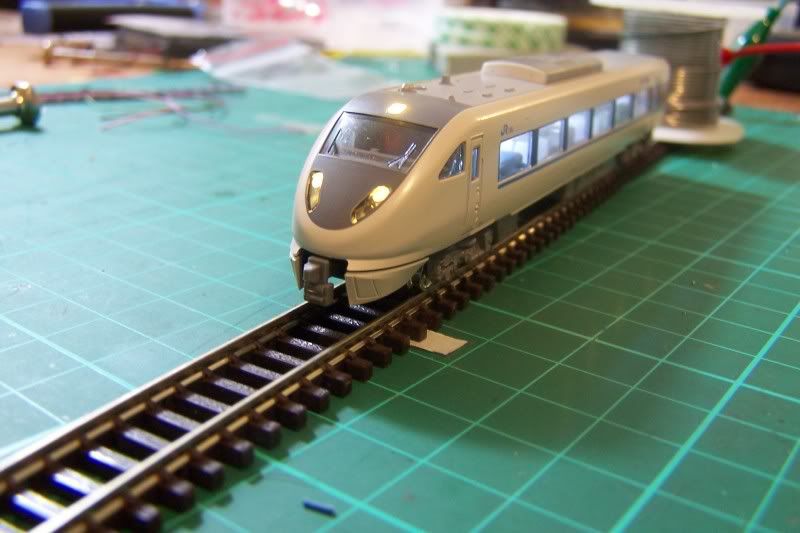
For the N Gauge fans. You do need to paint them for in gauge to help camouflage them, especially the flicker free unit.
Kato Tunderbird
Part 2 DCC Control and Flicker Free
That is your basic "Flicker Free" install the next part is about using a decoder to control "Flicker Free" giving you the ability to switch coach lighting on/off in 2 coaches but at the same time keeping the all the characteristics of "Flicker Free". It is not so much hard but very fiddly and time consuming.
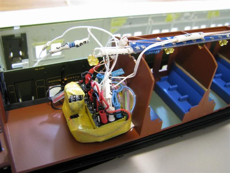
We are going to interface into the circuit good old micro relays. As some will know and it has being debated on here cap's corrupt the DCC signal. So we need to put the decoder in parallel with the capacitor. From there we use the decoder to control the relays which in turn control the on/off of the LED's. At any time if their is a problem with supply the capacitor takes over and supplies power.
The extras now you see in the picture are 1A DPDT micro relays and a TCS 4 function only decoder. You may notice in the first class compartments 2 seats are unpainted, something Hornby missed, no harm I will paint them later as well as the floor, to get slightly better light refraction.
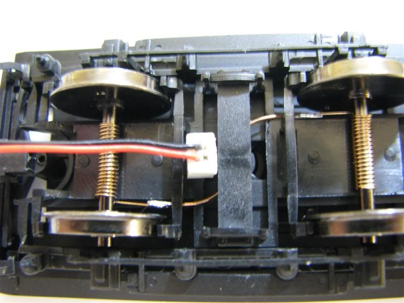
The coaches a brake and standard Maunsell coach have 1 wheel insulated so you dont need conductive paint. It also has slightly better access for the wiring through the bogie. To give the decoder the best chance possible I will also wire 2 bogies. We all know how sensitive DCC is.
Same again carefully strip down your coaches, identify and mark as necessary. The Maunsell bogies are finely detailed and I assume scale size. You got to be very careful removing the wheels as the frame is very thin. This time I was able to drill a small 1.5mm hole in the bearing which holds the bogie on and run my wire through that.
This photos shows the location of the plug so I can feed and control the second coach. It will be blackened later on along with the red wire.
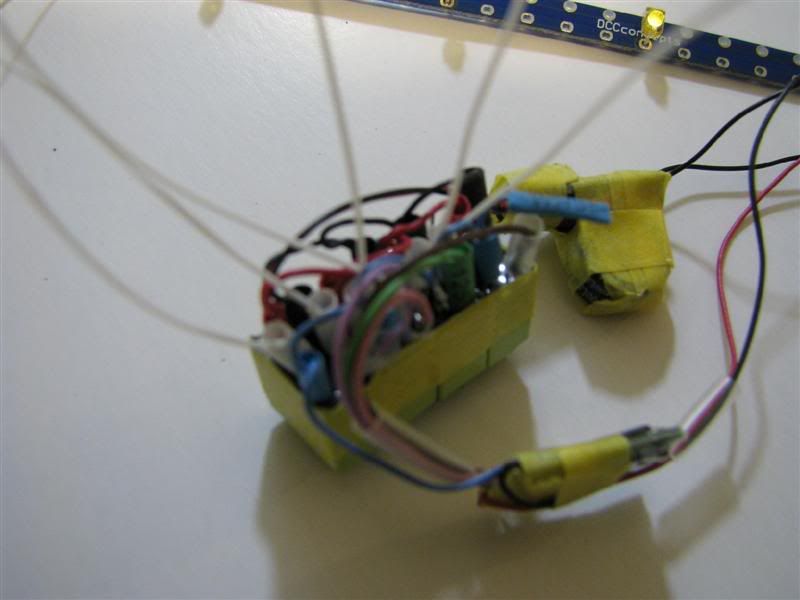
Next I built my control circuit and their is no easy way to describe this so I will do my best. Firstly I tested all my relays and taped 4 of them together. Thin all the terminals on your relays before you start, makes life easier. From there I added the blue wire on the control side and looped out to each relay. (Relay is polarity sensitive.) I then added my brown, green, pink and purple wire also on the control side of the relay. Gave it a test and made sure I could hear the coils in the relay moving. Remember the control side is DC from the decoder into the relay or it will not work, dont try to get them working on AC, it will not happen. There are only 2 wires left on my function only decoder red and black and they will be used for pickups.
Now for the power side. I wired my capacitor red wire into the common terminal and same with the black looping in and out from each relay. From there I added my wiring on the normally open terminals which will go out to my LED's. Lots of heat shrink to avoid shorts etc.
Once you are happy give the circuit a test and make sure it all works as it should. I was looking for the following:
Function 1, 2 and 3 actuated the correct relay and lights came on/off. On removal of power the lights stay on. The short video will explain it all. Notice on one end I used the full legs of the LED. This gets me lighting in here without using a second board. So thanks PT for that tip.
Wiring up the second coach is the same except it has no flicker free. It will be supplying 18 LED's on power failure. As you can see the plug is running out on one side. The only disadvantage to this is these 2 coaches have to work together but I think that's a small price to pay.
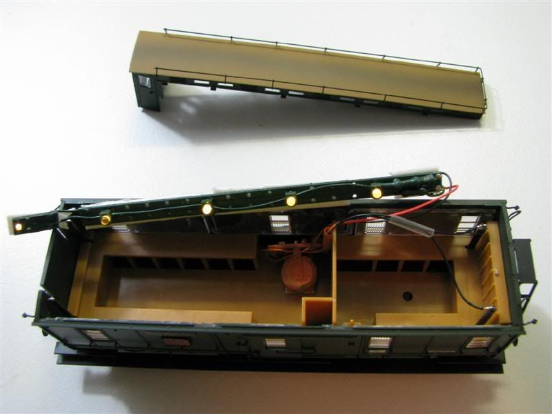
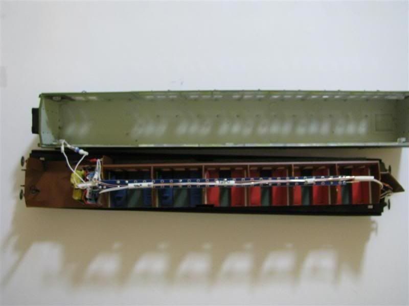
The Maunsell Brake coach is ideal for storing the control circuit. Unless you go looking for it you will not see it as it is hidden behind solid plastic. I used heat shrink to support some wires running along the board. They are the feed to the second coach and the pick ups from the other end. It keeps it neat. I also had to cut out small sections of the compartment walls as they go to the roof to allow the mounting of the board.
All that is left after 1 more test is to pop the lid back on. Watch the short video to see the results. I was very pleased and it easily shows "Flicker Free" can be used with a decoder. Before anyone asks no it is not suitable as an UPS for a loco decoder.
Link to very short video on youtube which shows lights on/off on 3 functions, what happens on power failure and then their is a video taken 1 minute later to show you 18 LED's still on on 1 "Flicker Free" unit. Sorry for the poor video but how else do I show it, you cannot see it in daylight.
http://www.youtube.com/watch?v=BYZ0zELwcho
Part 3 Technical Information
This will be short and sweet as I know some people may not be interested so instead of reading through it you can skip it.
Input 9-20v AC or DC or DCC. So you can run it on your layout as long as you do not go over 20v
Output to LED side 4.7v
Here is an interesting one I put a meter on it to measure current for the LED's Max draw was 25mA, yes 25mA for 18 LED's and the flicker free. So no need to worry about in rush current, you can have lots of coaches on your layout powering up. The coils in the relay pull more than the 18 LED's!
Capacitor storage 200,000 uF (that a lot for such a small capacitor, think of it as a battery)
A capacitor is a device that stores energy in the form of an electrical charge. It comes in all different shapes and sizes.
We then have Capacitance which is the ability of a capacitor to hold charge and the unit of charge is the farad (F), which is defined as follows:
A farad is the capacitance of a capacitor which stores a charge of one coulomb at a potential difference of 1 volt.
5th time constant I have worked out to be about 148 seconds using t=RC which means after 29.6 seconds the capacitor will be 63%charged, at 1 minute about 84%. It takes about 2 minutes to reach full charge.
Resistance is defined as opposition to current flow, and you need to put these in series with your LED's.
Flicker Free is available as follows:
FF-1
1 pack: 1x Flicker Free, 5x G/White LED, 1x Red
6 1,000 ohm / 1k resistors & instructions
FF-3
3 pack: 3x Flicker Free, 15x G/white LED, 2x Red
17x 1,000 ohm / 1k resistors & instructions
FF-6
6 pack: 6x Flicker Free, 30x G/white LED, 3x Red FF-6
33x 1,000 ohm / 1k resistors & instructions
BASIC Specifications from kit packet.
Input: AC, DC or DCC, 9~20 volts.
Connection: Pre-wired (150mm fine wires pre-fitted) and ready to connect.
Storage: Super Capacitor, 200,000 microfarads.
Output: 4.7 volts, current limited & protected
(already current limited and so safe for direct LED connection)
1 year goof-proof warrenty now that is confidence in your product!
I hope you enjoyed my review and feel feel to ask as many questions as you like.
Cheers
Martin