Just a quick photo log of how I fitted a pair of Seep point motors and a Digitrax DS 52 Stationary Decoder
[please excuse the slightly blurred pics in some of these but I can't retake them and they are clear enough for the purposes]
Assemble all parts and tools needed
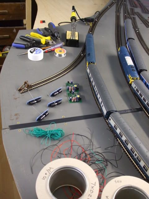
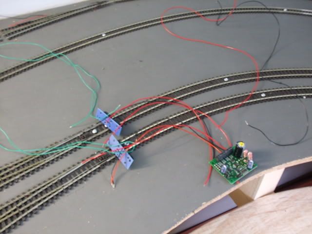
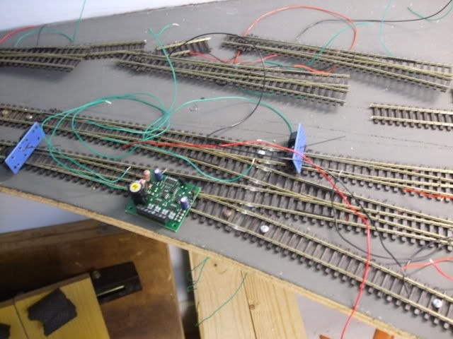
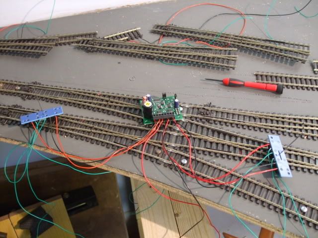
Lay out decoder and motors to see they don't foul droppers and each other, this also allows to measure roughly how long the wires need to be to and fro
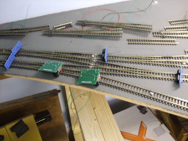
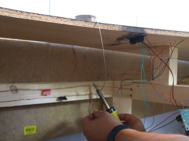
Double check under the board
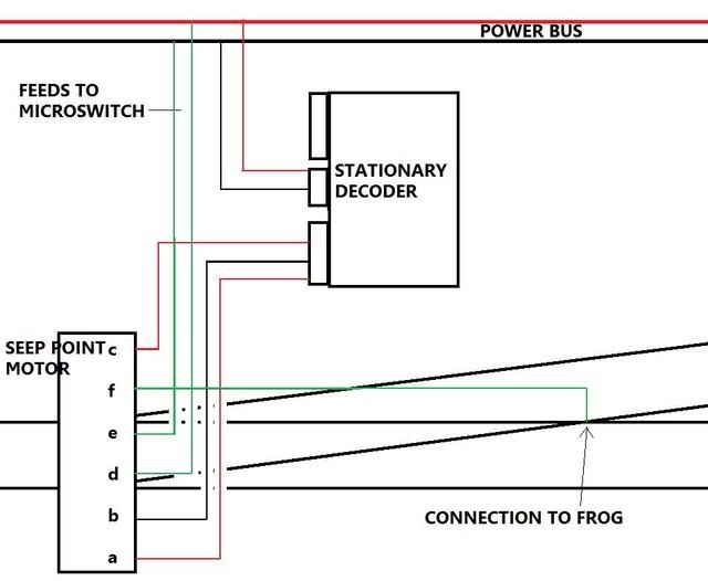
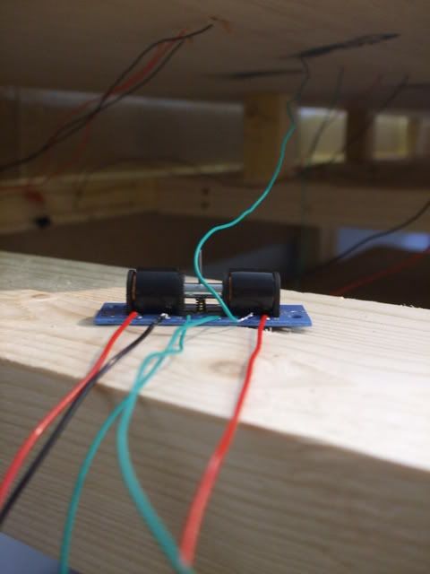
Cut all the wires needed [although blurred you can see the 2 red and 1 black between motor and decoder [x2] and the green wires for frog polarity. and the long red and black power lines to the bus]
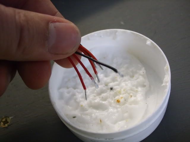
Tin all the wires [flux first]
Tin the motor contacts

Solder the wires to the motor, the red and black will go to the decoder, the green will go to the Bus for power for frog polarity switching
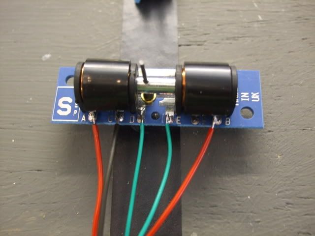
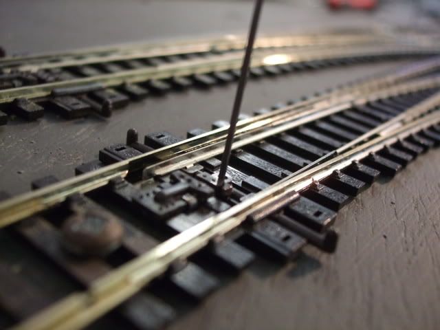
The last contact to solder [F] is the dropper from the point frog [which was done when the track was laid]
Wire into the decoder... nice and easy screw terminals [with the wire tinned for added strength]
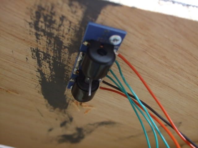
Locate the point motor.. making sure that it throws the point both ways. and screw in place
Solder power to the decoder from the Bus
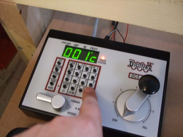
Check it works
Trim the motor arm
Solder the feeds from the point motor to the Bus
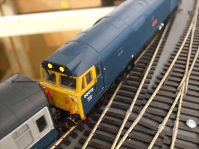
1st motor..Check for shorts with loco... don't get distracted here!
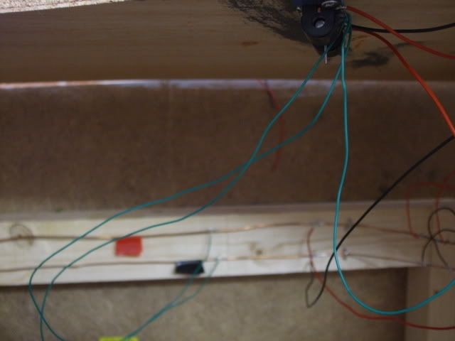
2nd one...ooo crazy reading on Zephyr =short.. so switch over those green wires on the Bus
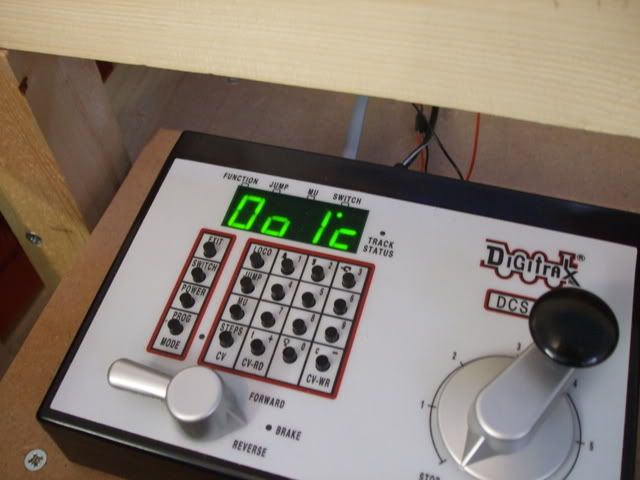
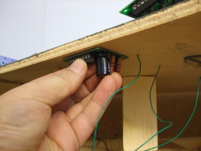
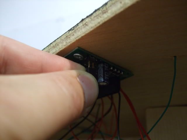
This little jumper is for programming the decoder addresses, closed to programme, open to operate
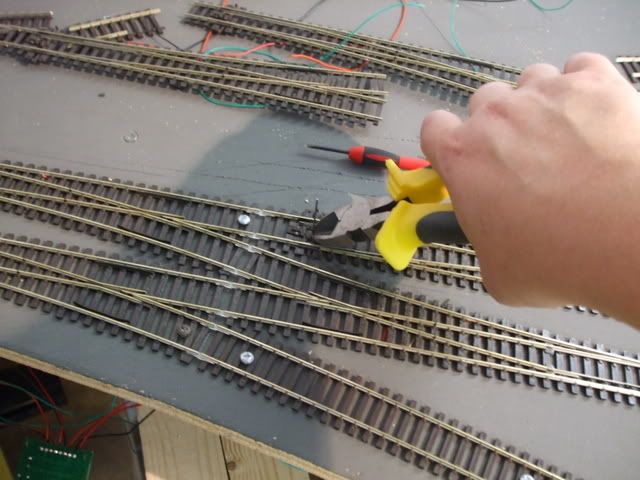
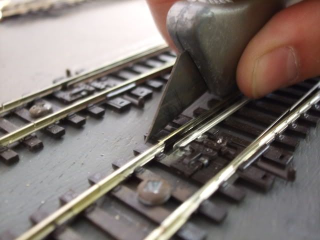
Nasty peco motor mounts.. trim trim trim
Job Done
Playtime!
My thread
Michael