Building a Control Panel With LED Route Indication

Articles which have been discussed in the main article section (7 days+) and are ready to be added to the main site.
mumbles
Posts: 1802
Joined: Sun Nov 12, 2006 11:23 pm
Location: Kent
Contact:

Building a Control Panel With LED Route Indication

Post by mumbles »

How to make a LED route indicator control panel for Electrically Operated Point Motors

This is by no means the only way but will hopefully point the reader in the right direction.

For this guide I am going to describe the technique I used for my DC control panel using specific items and materials but it should be emphasised that there are numerous products, methods and end results available to the modeller. I am not affiliated with any of the products used. D:

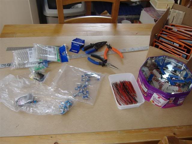
Items I have used are;
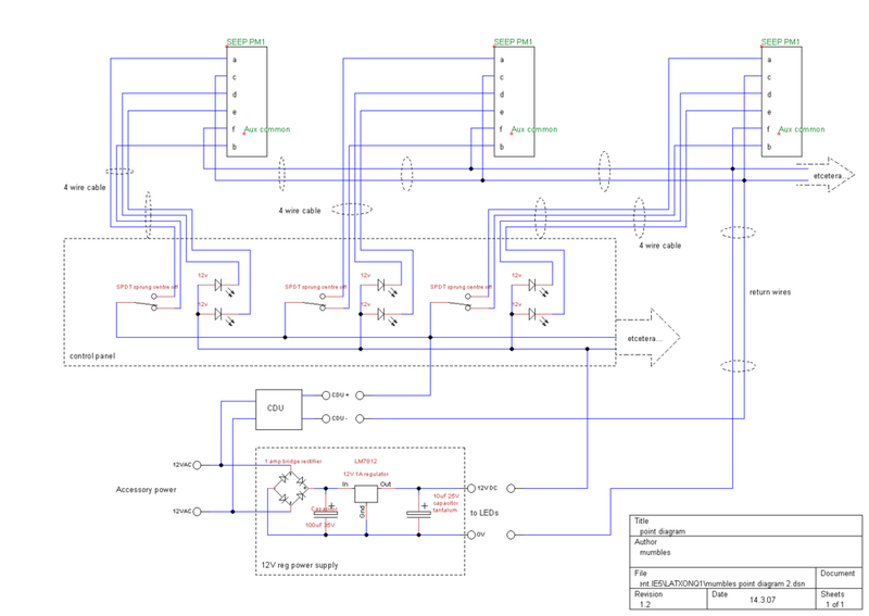
Point Motors: Gaugemaster Seep PM1 [From SignalBox]
Image
Panel Switches: Mini Toggle Switch (on)off(on) Spdt [from the Forum Shop]
Image
LEDS: 5mm 12v [from the Forum Shop]
Image
LED Holders: 5mm LED Panel Clip [from the Forum Shop, 3mm Pictured]
Image
Wire: 7/0.2mm [sourced locally]
Image
Terminal Blocks: 3amp [sourced locally]
Image

Wood for the panel itself

Solder, screws, paint, masking/insulating tapes and other various materials to build

I will describe the process I used to build the control panel itself first. I built it as an distinct unit that could be worked on away from the layout in the comfort and good light of my kitchen. When complete it could then be wired up internallywhich will I will describe in Part 2 of the article.
Part 3 will describe the external wiring.

PART 1: Building The Panel

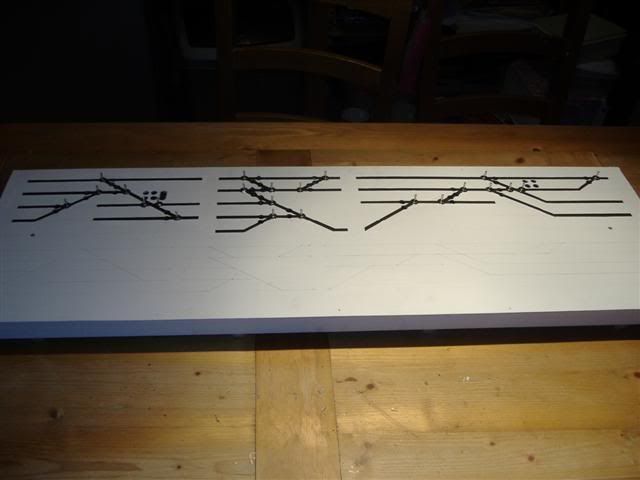
First I drew out a schematic for the track i was looking to 'control'. First on paper then transferred to the front piece of MDF for the panel [please note the top half only is for point control, the bottom half is for insulating sections]
Image
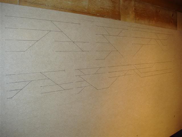
This was then painted white, and track was painted on. The method is used was maksing tape and painting, it would be esaier to use some sort of pen, however due to the size of my lines i decided to paint.

Construction of the panel was as per a baseboard, 1 1/2"x 1 1/2" bracing wood screwed to the 3mm MDF front sheet.

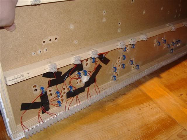
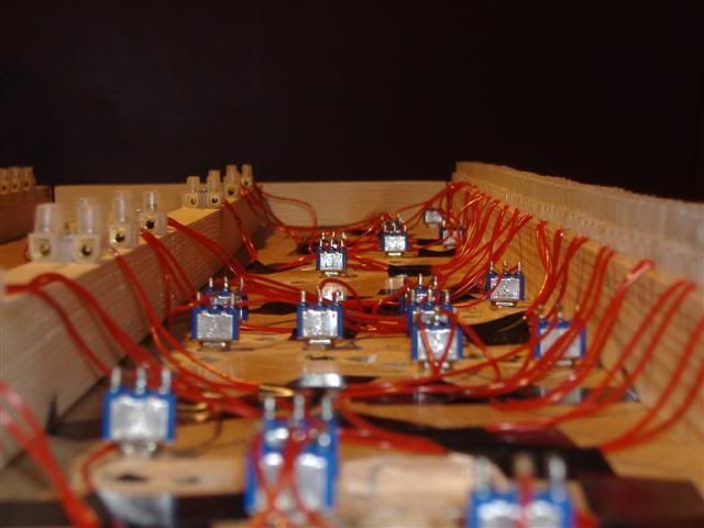
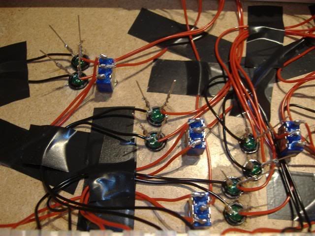
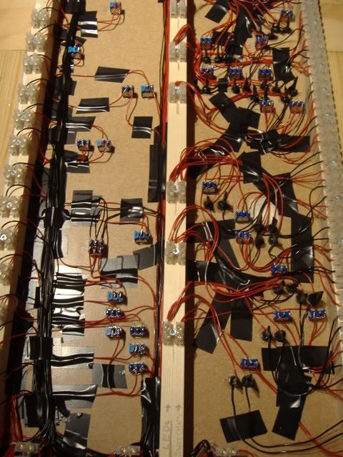
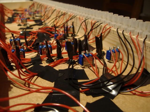
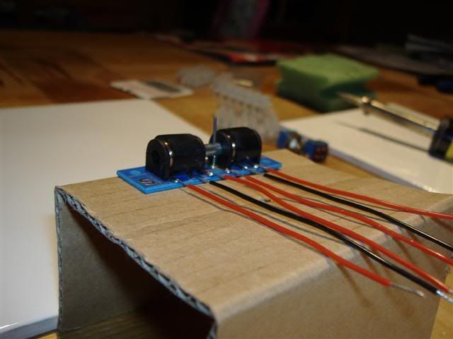
I had all the parts I needed to build this and although wiring point motors up comes in later, there is one job that can be done at this stage: soldering wires to the motors. As well this I wired these wires to chock blocks, to make wiring up the motors under basebaords easier. I made a small jig to hold them in a good position to work on.
Image
Image

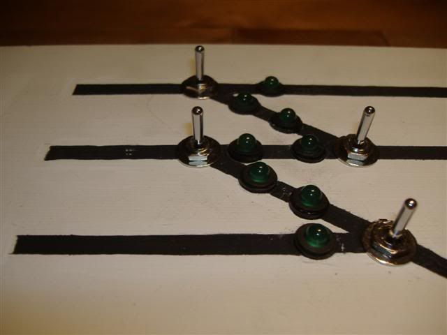
After painting and marking out track i drilled the holes for switches and LEDS [I may have drilled before painting actually, I can't remember!]
Then i began screwing in the switches and glueing in the LEDS.. I did not find a reliable glue for this.. I used Superglue and some LEDS are loose.
Starting to look right.
Image
When you have done all this prep work you can start to think about wiring it all up which will follow in Part 2 when i have found a decent version of the wiring diagram and re uploaded it.
Cheers
Michael
mumbles
Posts: 1802
Joined: Sun Nov 12, 2006 11:23 pm
Location: Kent
Contact:

Post by mumbles »

hi
just to say i didn't finish work till late today so part 2 may be a day or so coming...
cheers
michael
Chuffer Chuff
Posts: 528
Joined: Tue Aug 28, 2007 6:55 pm
Location: Warwickshire, West Midlands (Near The GWSR)

Post by Chuffer Chuff »

You have done Part 1 really well Mr Mumbles! As a result its inspired me to give it a go at some point!

Can't wait for part 2! Great Work!

Thanks :wink:
"You only get one chance in life, so make the most of it!"
m.levin
Posts: 2009
Joined: Mon Jan 09, 2006 6:46 pm

Post by m.levin »

What power did you use for powering the LEDs? AC or DC?
mumbles
Posts: 1802
Joined: Sun Nov 12, 2006 11:23 pm
Location: Kent
Contact:

Post by mumbles »

m.levin wrote:What power did you use for powering the LEDs? AC or DC?
i will cover what power i used more in the following parts, but just to say the point motors were powered by 16v ac through a CDU [not CDC] and the LEDs 12v dc.. these are both from the gaugemaster D controller that i have
michael
saslord
Site Admin
Posts: 259
Joined: Wed Oct 27, 2004 7:19 pm
Location: Peterborugh, UK
Contact:

Post by saslord »

Nice article. looking forward to part 2
mumbles
Posts: 1802
Joined: Sun Nov 12, 2006 11:23 pm
Location: Kent
Contact:

Post by mumbles »

PART 2: Internal Wiring for the Panel

Moving on to wiring up the switches and LEDs in the Control Panel, here you can see the wiring diagram :
Image
For this part i will focus on the wiring for this small part... which isn't complicated [rotated from main diagram to correspond with my panel photos better]
Image
until you see the switches and LEDs I have to wire!:
Image
The way I went about it, as there was so much soldering to do, was to do it in phases. 1st I wired up the switches. They are on the positive side of the 16v AC circuit so I used one colour [red] to wire from the power in, [top chock block on the middle baton] to the switch, then the 2 'throws' to the bottom chock block, taping neatly as I went.
This is an interesting picture as it shows the methodical way I have gone about wiring it up. With numbers for all switches/points and then correspondingly numbered chock blocks for the power in, I could have just used one chock block for the power in but if you have ever tried to feed a number of wires into one chock block you will know how hard it is to get much more than 4 or 5 wires into one. I split the points into smaller sections so as to ease them wiring into chock blocks, so no more than 3 wires went into each block.
[Figure A]
Image
Keeping it neat was paramount as if there was ever likely to be a fault I would be stuffed! Luckily this part of the build has never had a fault but with the numbering system i would be easily able to trace back to where it was coming from. See the neatness!!
Image
So having wired in all the switches I then fitted in the LEDS permanently [I think for previous shots they must have been for show!]
Then the process of soldering all these was next.
It may not be the best way but to solder the LEDs I wrapped the wire round, soldered and then trimmed down the excess leg of the LED, taping down as I went. Here I use red and black wire for my clarity [it may be technically wrong!] The red wire coming from the Middle Baton chock blocks, the black going out via the long row at the bottom of the picture above [Figure A]
Image

This shot shows the panel [with the right hand side being the focus of this article] To recap, taking as a starting point the Chock Blocks in the middle of the photo, these are the ones shown in the circuit diagram at top left. The wires for the LEDs [shown as one wire branching in circuit diagram, but 2 wires straight from chock on panel] go to the LEDs then to the Chock blocks on the right of photo [centre bottom on diagram] and the switch wires follow much the same pattern.
Image
and in close up, you can see how I have taped the LED legs to prevent shorts.
Image

That is what I did to construct the panel in the comfort of the kitchen, the next stage was to take it into the attic and wire it in to the layout. This will be the content of PART 3.

If you have any questions please ask them here, I tend to get a lot of PMs and MSN messages that to be honest I don't often answer due to the number. Especially with regard to this article as I know it is not going to cover all the aspects of making it.

Cheers
Michael
User avatar
SouthernBoy
Posts: 1753
Joined: Sun Oct 08, 2006 11:01 pm
Location: The past: We do things differently there

Post by SouthernBoy »

That's a really impressive, methodical, spaghetti junction you have there. Thanks for taking the time to post. One question from me: I read somewhere you should always 'tin' wires before you connect them to anything ... did you do this and does it make a difference ? / you didn't do this and it doesn't make a difference ?

Btw- I'm bookmarking this for future reference - it's really useful.
mumbles
Posts: 1802
Joined: Sun Nov 12, 2006 11:23 pm
Location: Kent
Contact:

Post by mumbles »

SouthernBoy wrote:That's a really impressive, methodical, spaghetti junction you have there. Thanks for taking the time to post. One question from me: I read somewhere you should always 'tin' wires before you connect them to anything ... did you do this and does it make a difference ? / you didn't do this and it doesn't make a difference ?

Btw- I'm bookmarking this for future reference - it's really useful.
hi
thanks SB
i didn't tin the wires, i wrapped them round the switch terminal /LED legs and heated with iron, applied solder and that was it. none of the connections have failed so far. they may well not be the proper way to solder but i got the job done ;-)

if i were to do it again i would get heat shrink to insulate the joins and it would be neater too

btw, i will try to finish this article in the next few days, not much more to describe, lots of wire this, wire that! a little more than that as i will explain the CDU and how it all fits together... stay tuned!
cheers
michael
User avatar
Roger (RJ)
Posts: 1567
Joined: Tue May 29, 2007 2:59 pm
Location: Nottingham, UK.

Post by Roger (RJ) »

I read somewhere you should always 'tin' wires before you connect them to anything ... did you do this and does it make a difference ?

Most electronic components are either pre-tinned or have a solder compatible finish so that they don't need tinning if you use flux cored solder.

EDIT: Sorry, I must remember to enable BBCode!

MODEDIT - Done for you in this post.
santene
Posts: 311
Joined: Mon Feb 25, 2008 6:46 pm
Location: middlesbrough

Post by santene »

makes me wonder why people ay 100-200 pound for a premade one
proud modeller jake also known as Duke Jake the Bewildered of Mousehole by Sea :D

anyone got n gauge track i can buy
PTmodeller
Posts: 965
Joined: Wed Sep 27, 2006 9:09 pm
Location: Preston, Lancashire.

Post by PTmodeller »

Hi Mumbles,
Did you use a socket so you can just plug it in upstairs?

Cheers
mumbles
Posts: 1802
Joined: Sun Nov 12, 2006 11:23 pm
Location: Kent
Contact:

Post by mumbles »

PTmodeller wrote:Hi Mumbles,
Did you use a socket so you can just plug it in upstairs?

Cheers
No
it was wired in via all the chock blocks.

one of thess days i'll take the photos to show the wiring involved in doing that, for part 3! :shock:

Michael
Last edited by mumbles on Tue Apr 15, 2008 11:15 am, edited 1 time in total.
PTmodeller
Posts: 965
Joined: Wed Sep 27, 2006 9:09 pm
Location: Preston, Lancashire.

Post by PTmodeller »

Cheers
Post Reply