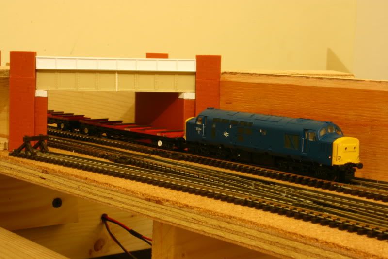
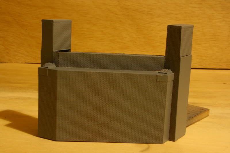
Building the abutments is turning out to be quite the challenge, mostly because of the awkward skew that I have decided to inflict upon it. I think it is needed though, otherwise this section of track is going to be a straight section of line sandwiched between two 90 degree over bridges. The skew is intended soley to break up this squared off look.
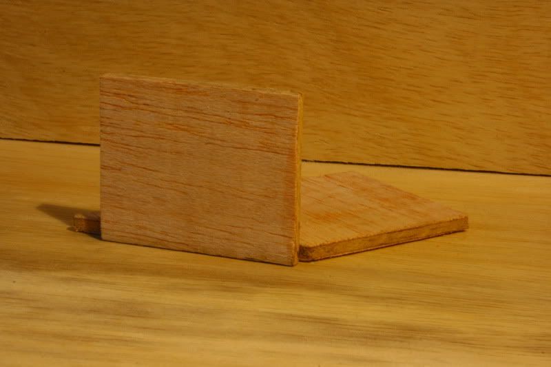
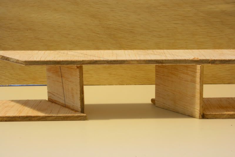
As with the small viaduct on the 00 colliery layout, I started with a very basic ply sub structure to get the skew angle right before committing anything to plasticard.
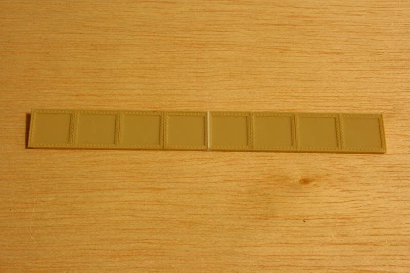
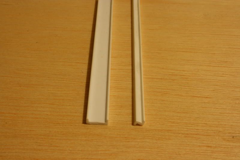
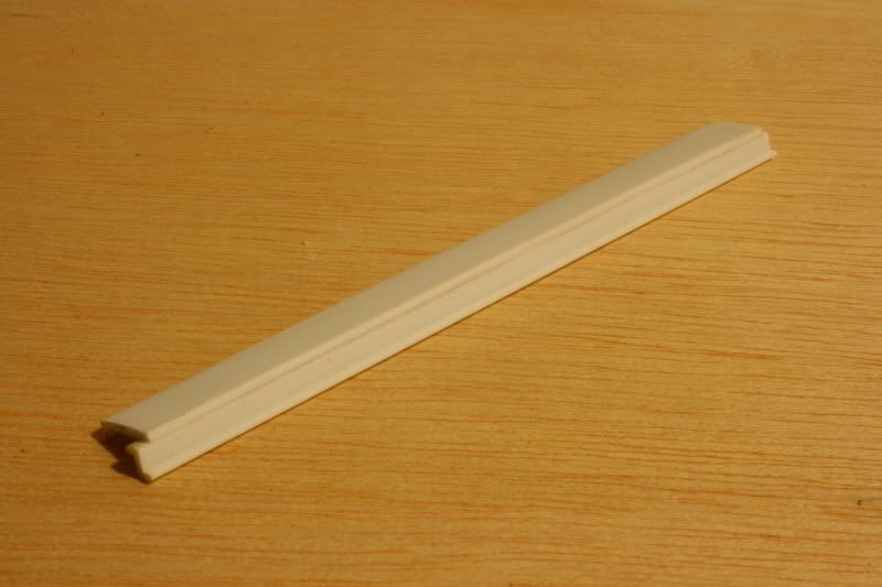
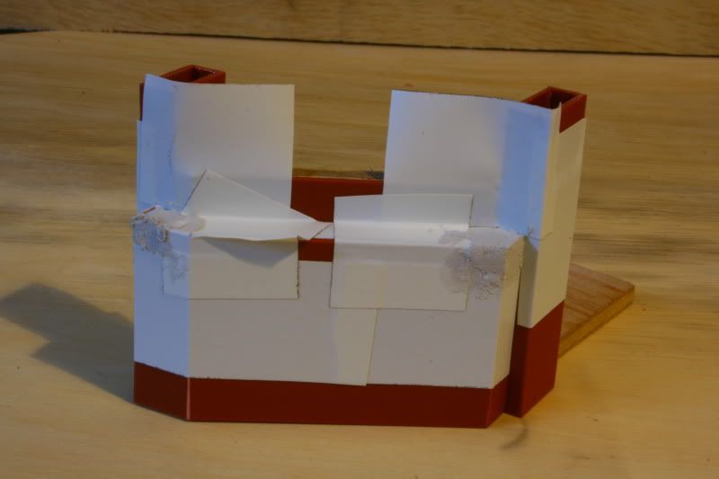
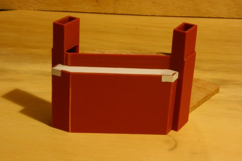
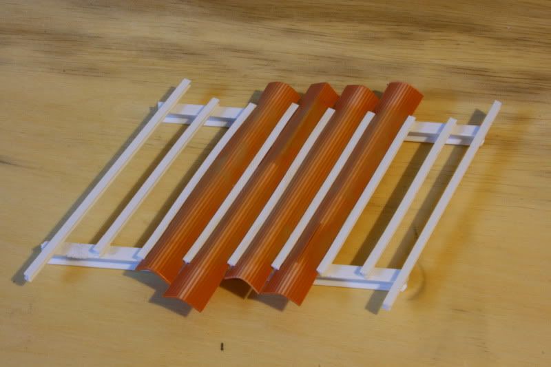
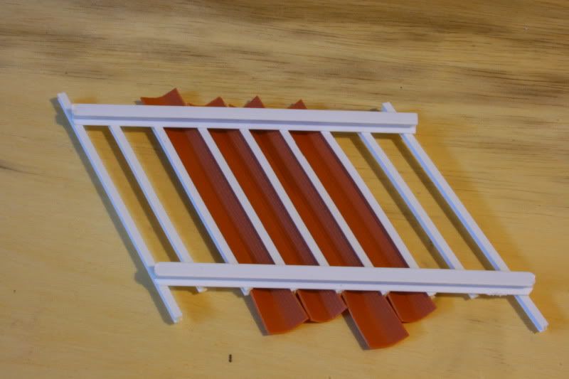
I began by shaping a template out of 9mm 'C' section. This will form the basis of the angles at the faceted end of the abutment as well as becoming reinforcement and the top surface of the abutment directly below the girders.
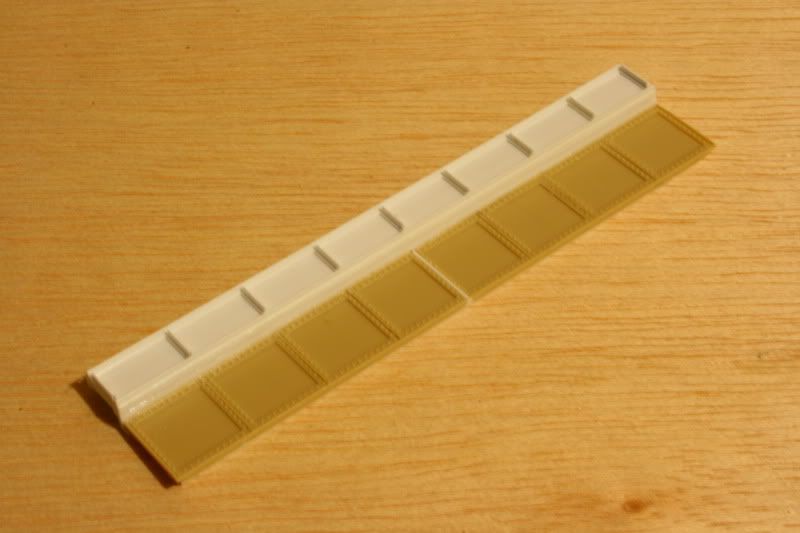
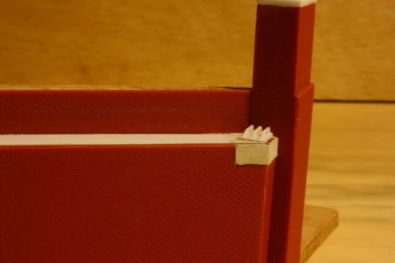
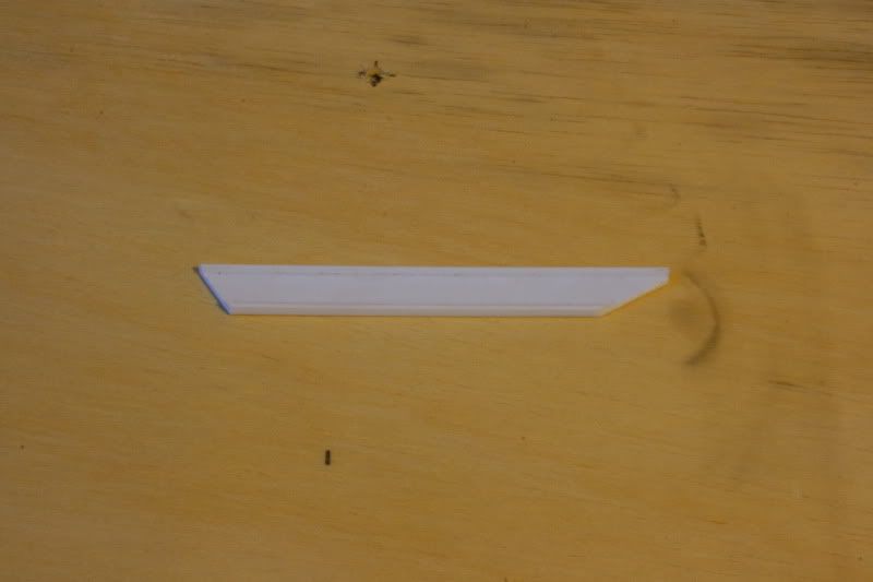
I then 'skinned' the template using plasticard of an adequate height. 37mm in this case with a 3mm gap between bedstone and girder with all edges mitred to give nice crisp corners to the brickwork.

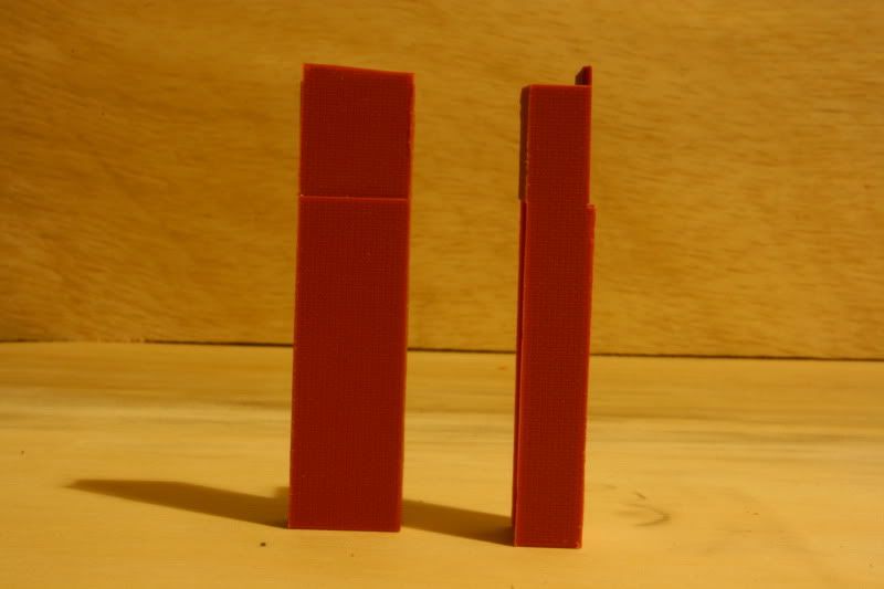
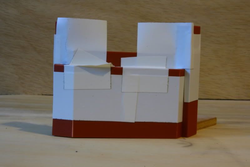
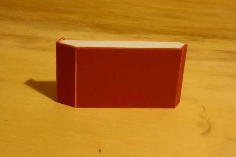
Once the supporting section of the abutment was completed, I turned my attention to producing the buttresses and parapets, and in this case have a slight step in the brickwork separating the buttress and parapet segments. Some additional decorative brickwork may yet adorn these pieces, I am undecided. Once the excess on the front edge is trimmed to the correct height, these assemblies will be ready to have a capping stone built up and fitted in place.
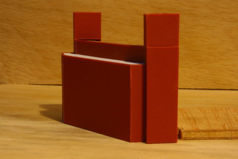
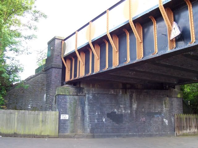
Owing to the skew angle, I observed the structure of several bridge abutments in the Birmingham area, and the main common feature I noticed with all of the bridges that weren't built on a 90 degree crossing is that the abutment where the angle is significantly over 90 degrees are faceted, constructed almost as a butress in some cases such as the Summer Lane bridge in Erdington, so that the bedstone supporting the girder in this location is fitted as a 90 degree piece of masonry, or very close to that. It has been trying to get these angles right which has been a source of problems and several rebuilds during this bridge build so far, but I think that this form is now pretty generic for a (Midlands) cantilevered plate girder bridge built on a skewed angle. Regarding the buttress/parapet wall, a number that I have observed do not have the girder recessed into the brickwork and it is the design of these that the bridge leans towards more than others, having said that, it would still be relatively easy to alter the buttresses to represent this other type.
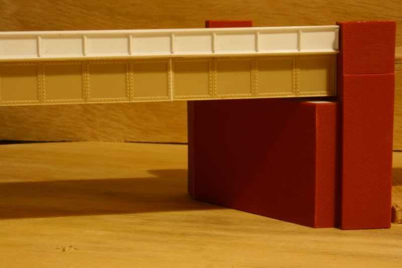
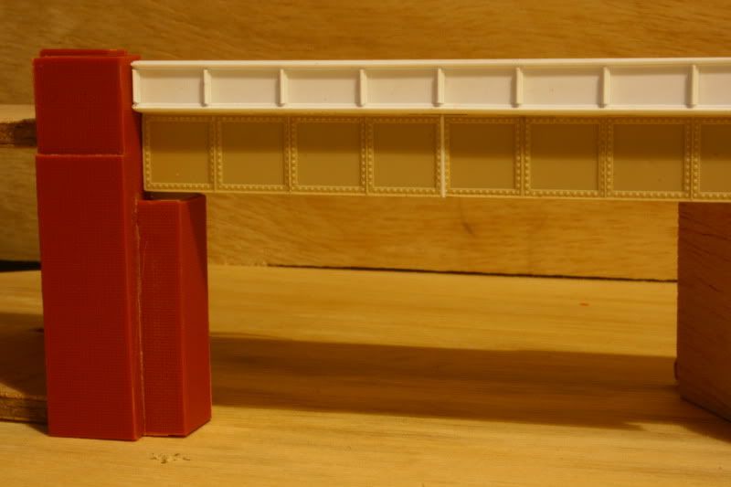
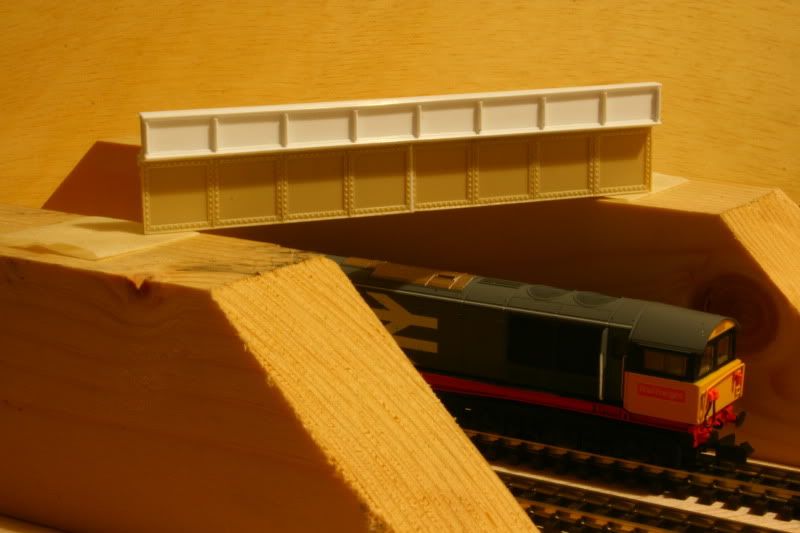
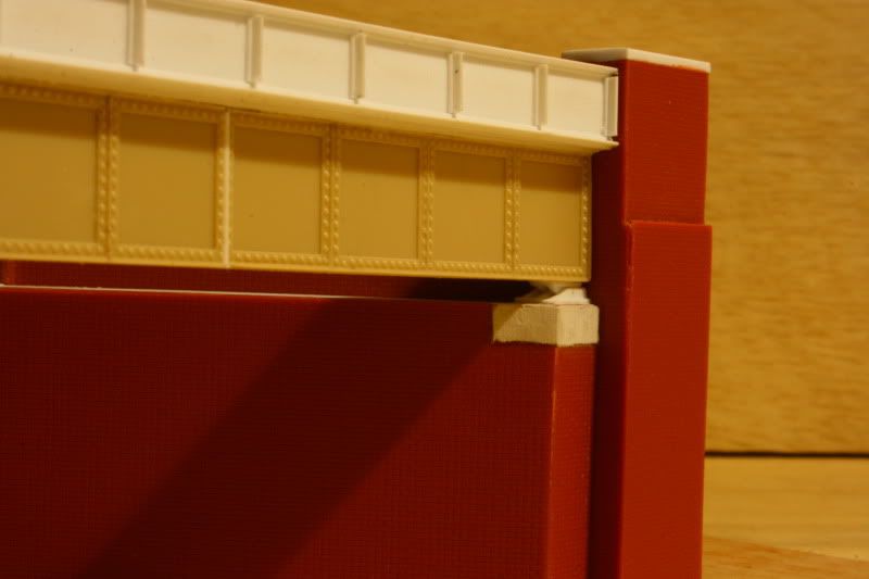
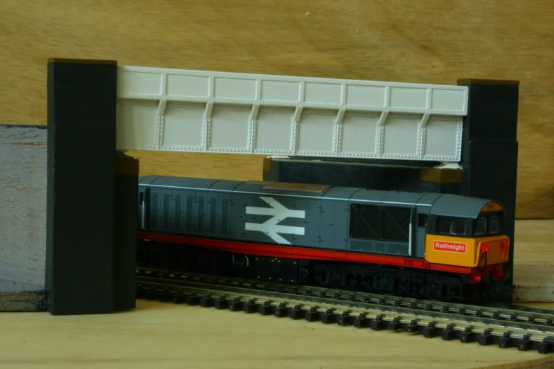
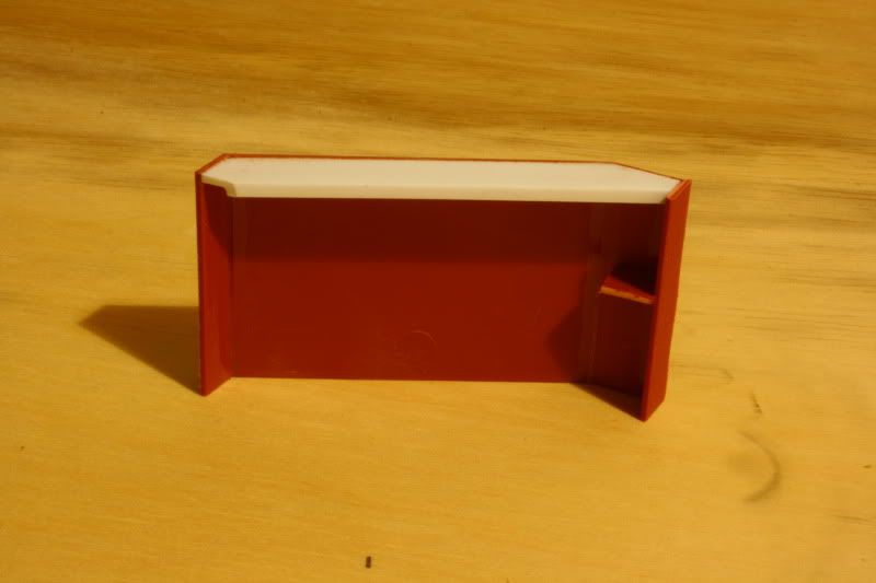
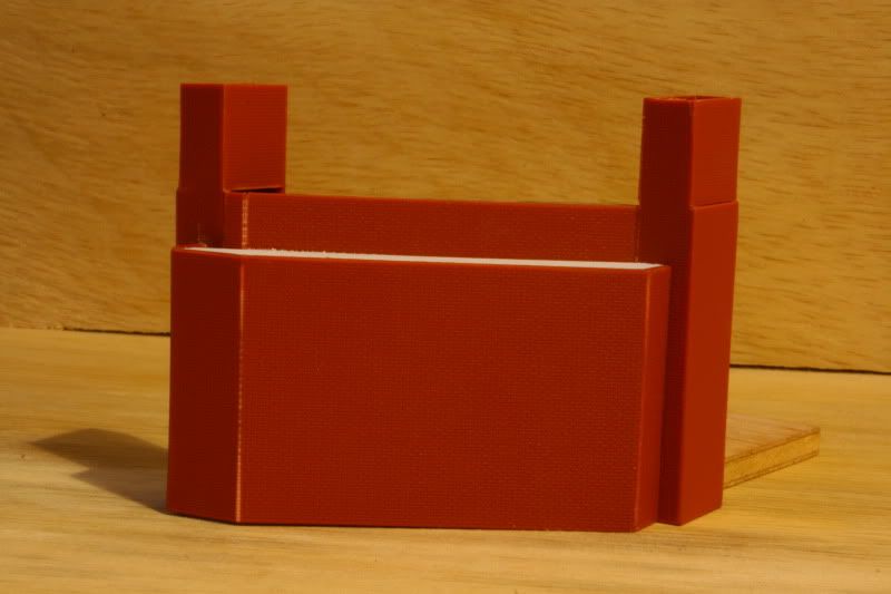
As can be seen, the girder sits a couple of mm above the stepped abutment. Each corner of the girder (once mounted to the trackbed) will have feet constructed which will seat it properly on to the bedstones, again a typical feature of many bridges of this type; but is in no means a compulsory feature. I've never built a bridge with this detail, so thought that its time I did one.

Now on the to do list is to build the other matching abutment, get the wing walls configured correctly to the form that the embankments will take, knock up all of the dressing stonework and bedstones, build the other side of the bridges girder (which I have yet to purchase another Kestrel water tower kit to butcher into), and to figure a way of adding all the rivet detail to the girder surface. As I build the other abutment it will be easier to recognise the photo worthy points in its construction, so will add in/edit this post to include them over the weekend as I continue the build rather than to sift through photos of me fumbling about trying to get the first abutment anywhere near a reasonable representation. A seperate post will be made to show how I produce the bedstones though as this in itself has a few steps.
Edit ~ additional stages in the abutment construction included into this post.