Going back to the first page, while the layout was still in the planning stage, I mentioned to
m8internet that I had a cunning plan in producing my upper storage loops. The method used is seldom used in the modelling world but it is common as muck in the construction industry, although the methods and materials are understandably very different due to the forces involved in 1:1 scale building.
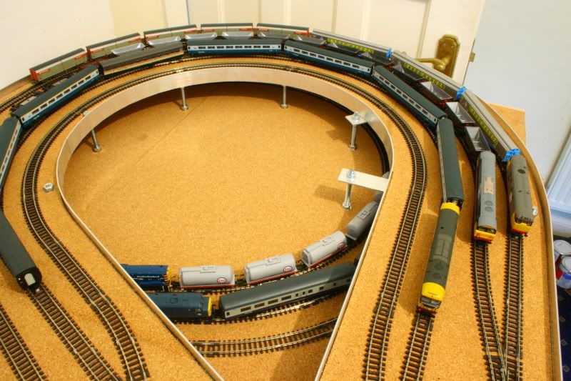
The loop uses a completely normal 9mm ply trackbed/baseboard which is 'pizzacuttered' to open out the baseboard surface to give access both inside and outside to the lower level storage loop. This effectively turns the baseboard here into one large 270 degree curved bridge. Owing to the tight clearance requirements below the baseboard level, a conventional framework is completely out of the question to retain the shallow 1:60 gradient (it actually works out at 1:56.8 due to slight changes in the location of gradient transitions and lengths). Of course, a 9mm thick ply trackbed that is just 165mm (6 1/2") wide and curved through 270 degrees is going to need substantial support, but with no allowance afforded to a framework
below the trackbed, I quickly sided with a framework built as part of the
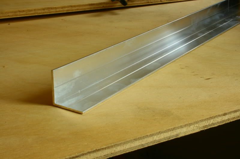
side of the trackbed which dictated that the material be very thin and also rigid. Wood is out of the question, its too thick and too much fuss to bend to the required radii at a thickness that would afford any support at all. Plastic is also a complete none starter due to the flexibility of thin materials, so I turned to metal. To keep things lightweight I opted for aluminium, and to fix sturdily enough to the ply it would need to fix to the underside of the board so it would have to be an 'L' section. Rolling/pressing aluminium to this shape isn't ideal, so I reached the final decision of using extruded aluminium.
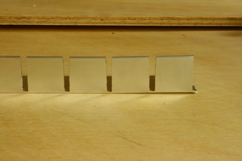
Naturally, metal in this shape isn't flexible, and my needs dictated that it be fixed to an inside radius that would fit inside 1st radius N Gauge setrack (9" radius) and provide clearance for lengthy stock which reduced the required radius to 8 1/4". Simple solution, slot the bottom lip of the 'L' section into 1" sections. Please note, at 10pm the neighbours do NOT appreciate the use of a 3mm grinding disc to cut dozens of slots into extruded aluminium. I wore ear defenders and STILL ended up with ringing in my ears!
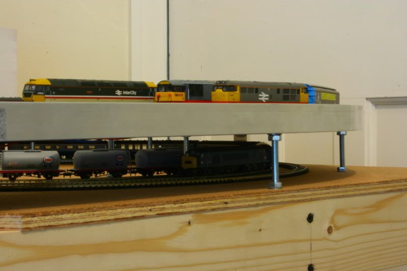
With several feet of 'L' section so treated, I then drilled out and countersunk each and every lip that had been cut so that I could go into overkill with 10mm long panel screws to fix the aluminium to the ply base. Where the rails of the lower level loop pass outside the bounds of the upper loop, I also formed several flat beams which fixed into place allowing me to bridge over the offending rails to fit the supports. These supports are simply formed with 6mm threaded rod, held in place with nuts and washers, which affords extremely fine tuning to the height, and then holds it all in place more than firmly.
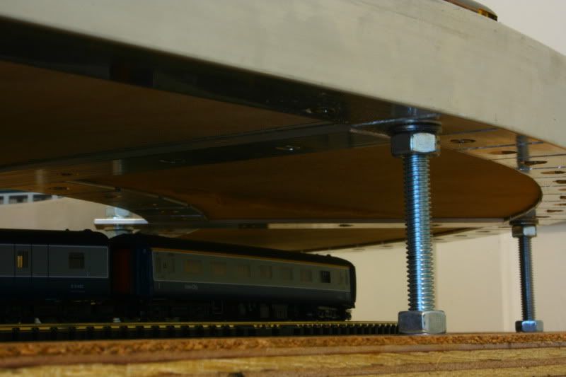
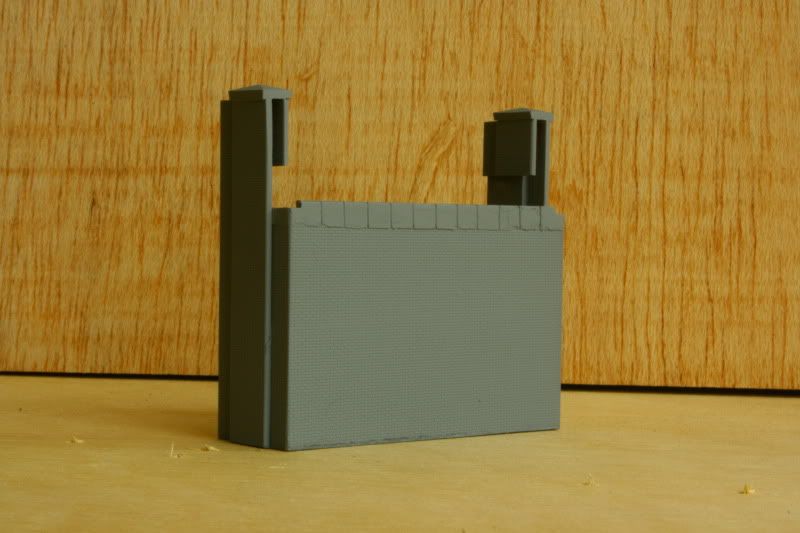
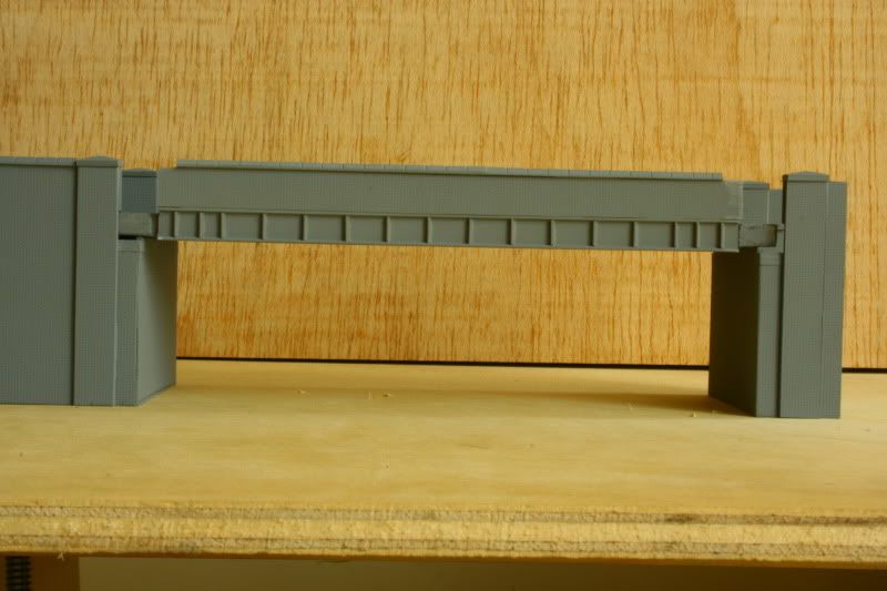
So, how does the finished product look?
And how strong is it? Well, I can push down on the apex of the board between supports and just about deflect it by 1-2mm with almost my full bodyweight. Lets hops all those screws can hold it in place if the ply ever decides to warp upwards, because it sure as heck ain't going to warp downwards...oh, wait...the nuts holding it in place are fixed at the top of the wood, so it can't go upwards either!

An added bonus to the design (completely by accident I hasten to add) is that the framework itself forms a barrier to stop derailed trains from falling over the edge too, which is a nice touch as it means I don't have to come up with something else to serve that purpose.