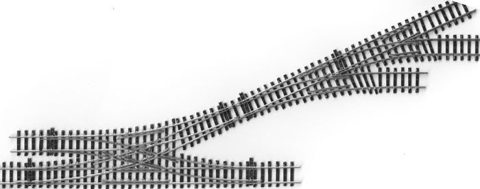
I thought that I would share my experiences of building my own points.
When I was thinking of building my first N gauge layout I realised that I was going to be limited for space. I decided that with the use of hand made points I would be able to fit point work into smaller spaces.
This is how I build mine, there are a number of systems that you can buy to make points but I am to tight to get any of those. I got my inspiration from a book called "Model railways on a budget" by Cyril J. Freezer, some of his suggestions are a bit out of date but it gave me some ideas on how to proceed.
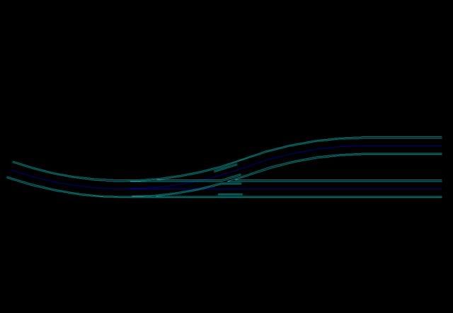
The first thing that I do is to create a plan of the center lines for the point on "Auto cad". I am sure that most CAD packages could be used it just happens that I used this one at work and got the hang of it.

Then I create the rails using an offset command.
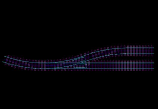
All that is required after that is to place the sleepers.
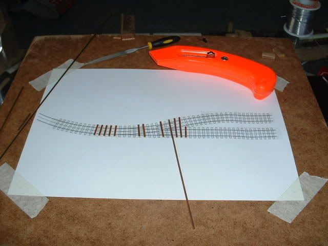
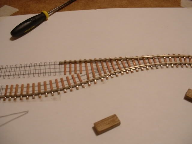
With the plan printed out full size and stuck to a board to work on I apply double sided tape along the center lines then place and trim the sleepers.
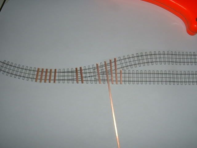
I then usually start with the longest and straightest rail. I offer it up, cut it roughly to length, and mark where any joggles should be.
A joggle is the recess in the stock rail where the point blade rests. Some people will bend the rail in a Z to create this, I decided that it was a lot easier to use a file.
Once the rail is done I tack it in place with the soldering iron.
I then do the same with the second rail, using the wooden gauges to ensure that rails are the correct spacing where they join.
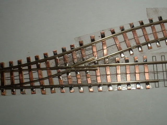
With the two stock rails in place I then work on the frog. Again I start with the straightest longest rail. File the end to a point, where the frog will be created. Don't worry to much about the angle, the second rail can be adjusted to fit and the important thing is that it meets as a point.
Use the two gauge blocks to get the frog point in the correct place, tack the frog using the soldering iron.
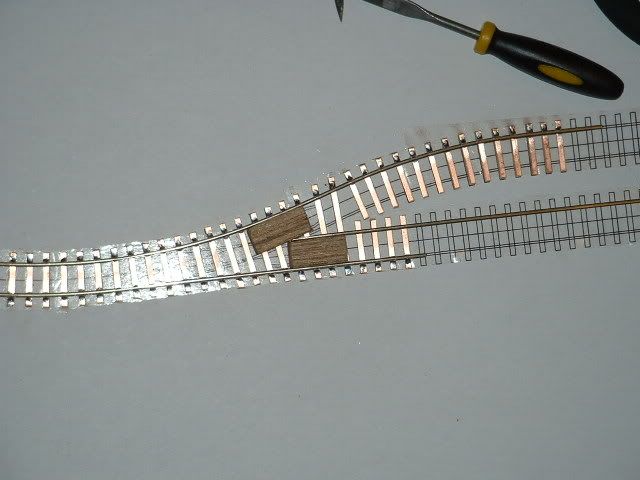
Create the second rail of the frog, offering it up to check how it fits. When soldering it in place use the gauges and I have found that the best way to solder it in place is to apply the iron to the top of the rail and feed the solder in to the open V of the frog. This does leave some solder on the top of the rail but gentle filing will remove this.
At this point I like to run a waggon along the tracks that I can. I try to use the wagon with the worst plastic wheels that I can, because if this fits all the others will.
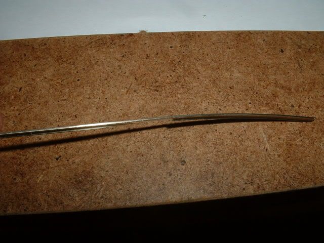
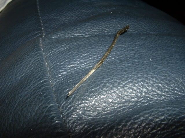
The next thing to work on is the blades. I usually start with the wing rails, bending them to shape. Where the blade and wing rail meet I usually saw the sides of the rail a bit to ensure a tight bend.
Once this is done I offer this up to the plan and cut the blade a little bit long.
Now this is the tedious bit as you need to file the blade to get it to have as long a taper as possible and to end up as thin as possible. The thinner the better your point will work, usually when I have finished this bit I can cut paper with the "Blade" rail.
Offer the blade and wing rail up to the point. If when the blade is set into the joggle the rail does not line up with the frog file a bit of the end of the blade to get it the right length. Once it is the right length solder the wing rail and a minimum of two sleeper away from the frog, this is to allow for the rail to be cut for isolation while still holding the blade in place. On the shorter points I usually file the sides of the blade down near the frog to allow the blade to flex more easily.
Again I run the waggon over the point to check the clearances.
Next add the check rails and ensure that the waggon fits still.
Also using a needle file I cut the copper on the sleepers to isolate the rails from each other and a jeweler's saw to cut the rail for isolation.
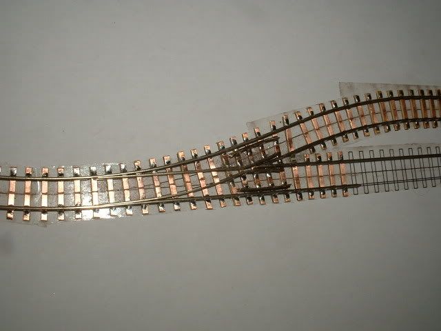
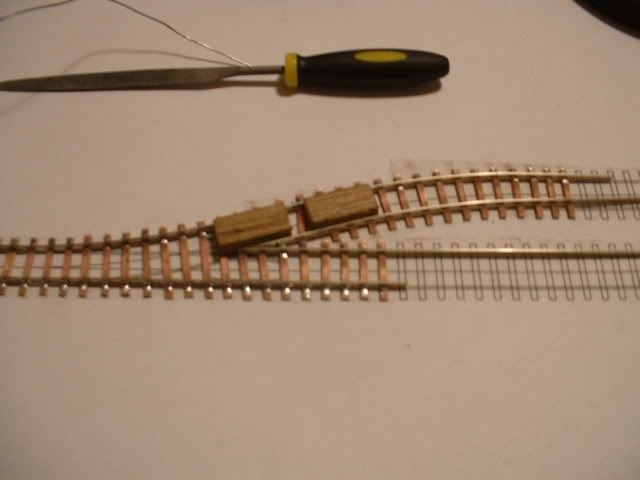
The tie bar is than added by spacing one of the blades away from the stock rail using something heat resistant and soldering this rail to the tie bar, then do the same for the other side ensuring the first rail is snug to the stock rail.
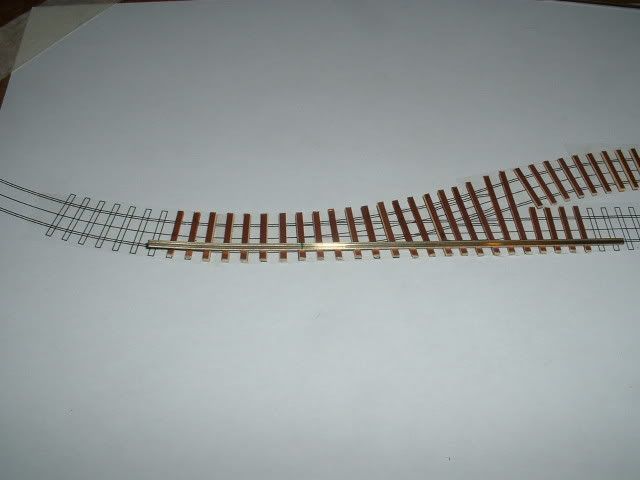
This point was for a hidden part of the track and has the same radius as a set track point but is electrofrog and has closer tolerances.
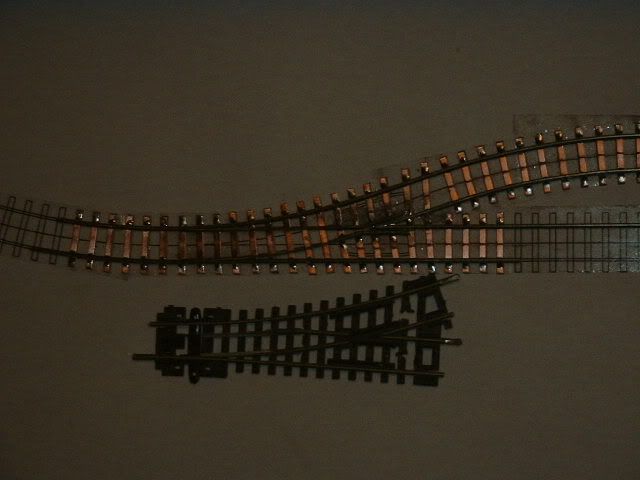
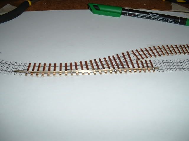
Once the point is finished I use a black marker pen to colour the sleepers as it easy to apply and is a very thin coating.
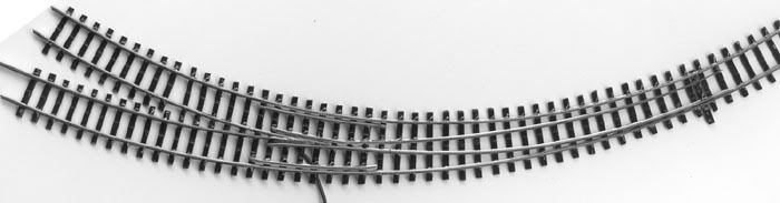
This is one that will be visible on the layout. One of the great things of building your own points is that you can make almost any thing you want. I have found that with a bit of patience you can do complex points.