DIY Motor Bogies

What are you up to on your workbench
Post Reply
User avatar
Bufferstop
Posts: 13819
Joined: Thu Mar 11, 2010 12:06 pm
Location: Bottom end of N. Warks line

DIY Motor Bogies

Post by Bufferstop »

With my coach project on hold I started looking into building a motor bogie. This was prompted by the appearance on the bay of a number of Triang BRCW DEMUs minus their motor bogie, at quite reasonable prices. Someone has obviously found a use for the double worm drive bogies, they are a very engineered drive unit but unless you can source some finer wheels you are stuck with the Ultrascale replacement sets which are a bit pricey but also have a long lead time. I'd been wondering for some time if the sets of plastic gears available very cheaply on Ebay could be used in a home brew bogie, with the frame etc 3D printed. I also bumped into the N20 format geared motors which can be had for under a fiver in a variety of speeds and voltages. If you haven't yet come across them they look like this.
N20 format geared motor.jpg
As you can see this one is from TangTangBuy's Ebay shop. There are loads of other dealers selling them and between them you can find almost any combination of output speed and supply voltage. They are just a bit longer than the old X03/4 sized motors. They do have one odity as far as we are concerned, they almost all come with a 3mm D profile shaft, the only exceptions I've found come with a long screwed rod which would be excellent for traversers, crossing gates etc.
Fortunately there are gears available to fit the shaft either 3mm bore or 3mm D bore. I suggest you do what I did Google "0.5 Module plastic gears". There's a bewildering array of them exceedingly cheap. I just ordered a selection and had fun sorting through them. For motor bogie use those with a 2mm nominal bore (usually categorised as turns freely on 2mm, or tight fit on 2mm and under 10mm diameter are the most useful.

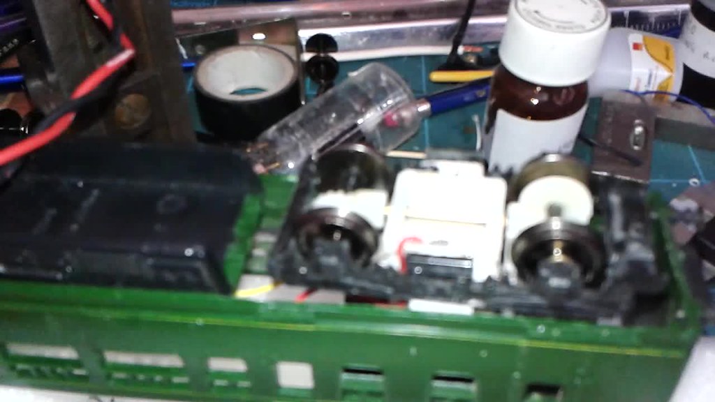
For my motor bogie I decided to use an old arrangement, I'd put a crown wheel on each axle, driven by a spur gear on each end of a shaft one to the left one to the right to ensure they both turned the same way. The one gear I used was combined with a larger gear which I intended to drive from a gear fitted on the motor shaft, but try as I might i couldn't get a choice of gears that held the motor clear of the gear at the other end of the bogie. So I had to put an idler in between.
Here's what I ended up producing
20180319_1218471.jpg
we have:
The motor with gear attached
4x 2mm top hat bearings
2x wheel sets with crown wheel gears fitted
then 3D printed
2x cosmetic side frames
a bogie frame
a motor mounting block, with the gear shaft passing through the bottom
a securing cap, upon which more later.
and this is how it looks put together, I haven't attached the cosmetic frames as this is to prove it works.
20180319_123036.jpg
Applying some power it turns, the speed range seems about right but maybe a little slow. Because the motor output shaft turns at a relatively low speed, and the spur gearing doesn't produce any end to end forces it just about holds together by friction fit which is fantastic for experimenting. The motor even stays in place without the top cap, which is convenient as that's from my first trial print, I've since changed some dimensions so it doesn't fit, besides which I want to modify it to hold the bogie mounting screw.
Now I know my limitations, particularly when it comes to long drawn out tasks, and even more so if someone else has already done the graft. So rather than turn to those cosmetic sides with spring and axlebox detail to be added I reached in the spares box and pulled out a Hornby bogie frame that had lots of lovely detail that I would struggle to reproduce. So I attacked it with a craft knife and removed most of the centre.
20180319_125141.jpg
Some cleaning up with a file and I was able to try a first test assembly,
20180319_124851.jpg
Hornby bogie mouldings are definitely more slippery than 3D printing so I can't try it out until I've done some more work on the frame devising a fixing for it and adding some strengthening to the end where the coupler had been, as its removal has left that end a bit weak. Still it all fits. I'll be reporting back when it has run under its own power, hopefully with a DMU body sitting on top. The gear on the motor shaft is still only pushed on, the built in gearing produces enough torque to turn the shaft within the gear if I hold on to it, which promises a decent amount of hauling power.
If you want to know more about these motors purely by coincidence there's a good article about them in the April Railway Modeler.
Growing old, can't avoid it. Growing up, forget it!
My Layout, My Workbench Blog and My Opinions
User avatar
Mountain
Posts: 5881
Joined: Mon Oct 24, 2016 3:43 pm
Location: UK.

Re: DIY Motor Bogies

Post by Mountain »

Wow. Now that is impressive. Not read what you put yet! Just looked at the pictures! :D Will read now....
User avatar
TimberSurf
Posts: 2537
Joined: Wed Jan 08, 2014 5:47 pm
Location: N.Wales
Contact:

Re: DIY Motor Bogies

Post by TimberSurf »

I have been buying these motor/gearbox's for a couple of years, I use them to drive my animotion mechanisms. I always wondered if they could be a replacement for hornby cans without the worm! Will watch with interest if they work out. What was the RPM version you have?
Others, be weary they come in 3v and 6v variants that won't survive track voltages!
Image
Lumsdonia <--- Hit link to go to my website for full story and wiring advice!
User avatar
Bufferstop
Posts: 13819
Joined: Thu Mar 11, 2010 12:06 pm
Location: Bottom end of N. Warks line

Re: DIY Motor Bogies

Post by Bufferstop »

That motor's a 6V 300rpm one, once I've finalised the design I'll order a 12V one of whatever speed will be best. I picked up this one at an exhibition a couple of years ago. They are slightly longer but lower profile than the old X03 but the problem comes with that 3mm shaft, otherwise they'd be a drop in cure for the pocket rockets. In his article in the Railway Modeller Geoff Heliwell describes how he mounted the gear shaft in a lathe and turned it down to fit a normal set of gears, I don't run to the lathe hence my choice of mounting the motor at the top of a gear stack. These motors are used inside remote control door mirrors and even central locking systems, so they have no shortage of grunt. I have a second design for a bogie, well it's hardly mine, it's a straight copy of the Triang design using cheap 12V double ended motors, but it would need high ratio worms and gears, that needs much more accuracy of construction and two gear sets does bump up the cost rather, compared to the bumper packs of Chinese plastic ones.
Growing old, can't avoid it. Growing up, forget it!
My Layout, My Workbench Blog and My Opinions
Admin4
Posts: 1901
Joined: Wed Nov 14, 2012 4:39 pm

Re: DIY Motor Bogies

Post by Admin4 »

Really fascinating stuff, I’m following with interest!

It’s going to be a silly question I am sure but what are all the gears already attached to the motor for? When I first spotted them I assumed you needed to mesh your gears with them but they look like they are before the shaft

I just don’t recall seeing a motor like that before (probably have & it’s probably been hidden inside motor casing)

At any rate keep up the good work :D
Bigmet
Posts: 10248
Joined: Tue Aug 14, 2007 2:19 pm

Re: DIY Motor Bogies

Post by Bigmet »

Great project, thanks for showing it. As an alternative, the motor and gearbox unit looks small enough to be half buried in the floor for concealment, with a shaft drive to the bogie.

Equally applicable in tiny early steam locos: motor in tender, driving the loco wheels via a shaft.
User avatar
Mountain
Posts: 5881
Joined: Mon Oct 24, 2016 3:43 pm
Location: UK.

Re: DIY Motor Bogies

Post by Mountain »

alex3410 wrote:Really fascinating stuff, I’m following with interest!

It’s going to be a silly question I am sure but what are all the gears already attached to the motor for? When I first spotted them I assumed you needed to mesh your gears with them but they look like they are before the shaft

I just don’t recall seeing a motor like that before (probably have & it’s probably been hidden inside motor casing)

At any rate keep up the good work :D
These have been sold for a number of years in hobby stores and places like Maplin etc. They have what looks to be nice motors couples to lovely gearboxes, and were intended to be sold to customers who are into robotic animation etc. Actually anyone who needs them for a project. They come in varying voltages from 3V and up. (3v,6v,12v seem to be the most popular). They also come in different sizes and with different gear reductions. Due to the normal intended use, most of them tend to be geared down a bit too low for model railway locomotive use without them being geared back up a bit. (It also explains the wide output shaft).
I've never bought one myself but have been everso tempted to! I was thinking along the lines of finding a way to take the gears apart and swap things around!
User avatar
Bufferstop
Posts: 13819
Joined: Thu Mar 11, 2010 12:06 pm
Location: Bottom end of N. Warks line

Re: DIY Motor Bogies

Post by Bufferstop »

Alex they come as a unit motor and gearbox, configured to give the rpm requested by the intended user. They are obviously being made in large numbers for industrial users the 12V specimens coming courtesy of the auto industry. They gearbox is actually attached to the motor by some very small brass screws making them interchangeable, so providing you don't mind buying two, for around a tenner the pair, you can make your own combination of motor voltage and gearbox type. The degree of accuracy required with spur gearing is less than we are used to with worm drives but even so i doubt my ability and resources to turn that shaft down to 2mm or so. From time to time someone advertises the gearbox in its own, I might just have to acquire one and experiment with replacing the output shaft with something more useful. If you can find bevel gears of sufficiently small diameter you could drive straight onto the axle of a steam loco. It seams a shame to even think of attaching them to an inefficient, noisy metal worm gear. One thing I haven't mentioned so far is that as supplied even at full voltage they are exceptionally quiet which says a lot about the quality of those little gearboxes.
Growing old, can't avoid it. Growing up, forget it!
My Layout, My Workbench Blog and My Opinions
Admin4
Posts: 1901
Joined: Wed Nov 14, 2012 4:39 pm

Re: DIY Motor Bogies

Post by Admin4 »

That explains it, I can see the benefits - using good old model railway ingenuity to repurpose things :lol:
User avatar
Bufferstop
Posts: 13819
Joined: Thu Mar 11, 2010 12:06 pm
Location: Bottom end of N. Warks line

Re: DIY Motor Bogies

Post by Bufferstop »

The 12V motor arrived it was easy enough to swap it in as all the dimensions that matter are the same. It confirmed my suspicion that it may turn out too slow. It was, but with the supply of gears I had i thought I should b able to get it turning the wheels at an acceptable speed. I produced a new version of the central mounting block which had a vertical slot the width of the motor, this allowed me to slide the motor up and down and pack it above and below with pieces of plasticard. this is how it looked
20180319_124851.jpg
and this is how it looked by the time I'd got the gear ratio I wanted
20180330_141134.jpg
That big gear makes it rather noisy, Here's how it looks from below once I'd added some pickups, phosphor bronze wire melted into the plastic
20180330_141321.jpg
and you can even see it running, but first mute your sound or turn it right down, I have a new improved version of my video software and it tries to set the sound level automatically and I can't find where to turn it off.
ImageBogie Bench test by John Williams, on Flickr

and here it is installed in the DMU I acquired minus motor bogie, there were four or five in various conditions all minus the motor bogie, this one was cheap and not the most expensive.
ImageDMU first trial by John Williams, on Flickr

I'm still waiting for small tiny universal joints from Ebay, There's loads of room under the body to use one of these motors or a double ended version of the type 7, could do with finding some sub 10mm bevel gears then the gearing could be simplified, and laid out as the prototype.
Growing old, can't avoid it. Growing up, forget it!
My Layout, My Workbench Blog and My Opinions
User avatar
TimberSurf
Posts: 2537
Joined: Wed Jan 08, 2014 5:47 pm
Location: N.Wales
Contact:

Re: DIY Motor Bogies

Post by TimberSurf »

The possibility of a 2018 comp has been stirring idea's for what to do! I have come up with a plan to develop a locomotive from scratch. {The designers at the Lumsdonia traction workshop think they are smarter than all the well know engine manufacturers :o }. The external body shape and the power plant will be revolutionary :P {read experimental}. So I could just rehash an old engine and repurpose, but for such a radical looking engine, it would be nice to make my own bogies. I did a little research and those motor/gearbox's are available in 12v at 200,300,400,600 and 1,000RPM output speeds.
Can we do the maths and work out what speed is needed? Let's aim for 100mph.
Image
Lumsdonia <--- Hit link to go to my website for full story and wiring advice!
User avatar
TimberSurf
Posts: 2537
Joined: Wed Jan 08, 2014 5:47 pm
Location: N.Wales
Contact:

Re: DIY Motor Bogies

Post by TimberSurf »

So

1 mile = 5280 ft
100mph = 528,000ft/h = 528,000/60 = 8800ft per min

for a 12mm wheel = 37.70mm circumference = 9.425ft circumference
8800/9.425 = 933.7RPM

for a 14mm wheel = 43.98mm circumference = 10.996ft circumference
8800/10.996 = 800.3RPM

So 400RPM or 600RPM (without a raised ratio) will give shunter performance, mainline engine will require the 1,000RPM version
Image
Lumsdonia <--- Hit link to go to my website for full story and wiring advice!
User avatar
Bufferstop
Posts: 13819
Joined: Thu Mar 11, 2010 12:06 pm
Location: Bottom end of N. Warks line

Re: DIY Motor Bogies

Post by Bufferstop »

Though it was time for a update on these. Had a lot of interference from real life so progress hasn't been too rapid. When I'm fitting them in whenever I never remember to take photo's as I go along. First up is a version I built using a Hornby type 7 motor and two sets of 0-4-0 worms and gears. Fitting gears intended for Hornby driving axles onto 2mm rolling stock axles is easier than it sounds, you need a 1/8th axle bearing and a 2mm frame bush. Ease the edges of the axle hole on one side of the wheel, press the 1/8th bearing in just for enough to stay, then put the wheel and bearing between the jaws of the vice, and tighten it up, until the face of the bearing is against the face of the wheel. Then put the 2mm bush in from the opposite side and repeat the process. You'll find it is a sliding fit on a 2mm axle, it will need a drop of threadlock or superglue to finally fix it in place.
I used more 2mm frame bushes as bearings, and that's where I made a mistake, of which more later. I used a pair of Chinese nylon gears to give a roughly 2:1 reduction ratio and fashioned pickups from phosphor bronze wire melted into the plastic. here it is.
Type 7 motor bogie.jpg
My mistake, the flange of the frame bush is about the same diameter as the central boss on the wheels, set up with the absolute minimum of sideplay on the axle it repeatedly made sufficient contact to short across the axle to wheel face. A sliver of clear tape on the face of one bush on each axle cured it. I think the proper fix would be to reverse the bush in one of the wheels. I'd swear that biasing the wheels one way they only make contact at one end at a time, but rolling it down the track without the worms fitted demonstrates that current manages to flow across. I can only assume that when it looses contact with the bush on one side the current arcs long enough to make contact the other, probably down to the motor back emf.
Despite the 2:1 reduction the type 7 motor lacks torque, it might be ok for a single coach DMU but pulling power isn't great.
Next up an almost identical bogie but fitted with a Hornby 0-4-0 can motor. Well it would be pretty similar, it contains about 70% of the parts from the type 7 version, just a different motor and reduction gears.
Can type motor bogie.jpg
I 3D printed a new central bracket for the motor and re assembled it with the new motor installed. This one's actually showing some promise even with the 2:1 reduction the 0-4-0 motor and gears still perform "scalded cat" starts, so I may play around and see if I can raise that ratio a little, hopefully without raising the noise level which isn't bad, a diesel like purr. There's still a couple I want to try a centre motor drive with universal joints, (they've arrived) and I thought I ought to see if I really can make a better job than the ringfield bogie using a CD tray motor.
Growing old, can't avoid it. Growing up, forget it!
My Layout, My Workbench Blog and My Opinions
Post Reply