MY NEW LAYOUT ARDUINO CONTROLLED

Post pictures and information about your own personal model railway layout that is under construction. Keep members up-to-date with what you are doing and discuss problems that you are having.
Post Reply
timbologist
Posts: 372
Joined: Wed Sep 18, 2013 6:39 am
Location: Hazeldene Victoria Australia ( in the bush )

MORE THE COAL STAGE

Post by timbologist »

Hi all

Coal stage is gradually getting there, the 3D printer has been hard at work, squirting plastic. So I have been gradually started painting sorting out the colours.
When I paint the ABS plastic I thin the Humbrol paint with Acetone it give it a better bite into the plastic. Plus it makes it dry a bit faster.

Just started to design and print some modes to a Lima 4 wheel Diesel to turn it into a powered track cleaner, will be just using the powered chassis.
Will have some photo's of this set up in a few days hopefully all going well. :)
coal stage
coal stage
P2040052.JPG (173.38 KiB) Viewed 2351 times
coal stage
coal stage
P2040051.JPG (155.31 KiB) Viewed 2351 times
coal stage
coal stage
P2040050.JPG (170.53 KiB) Viewed 2351 times
Lima body
Lima body
P2040054.JPG (158.38 KiB) Viewed 2351 times
Lima powered chassis
P2040053.JPG (152.84 KiB) Viewed 2351 times
timbologist
Posts: 372
Joined: Wed Sep 18, 2013 6:39 am
Location: Hazeldene Victoria Australia ( in the bush )

WROUGHT IRON WORK

Post by timbologist »

Hi all

Well go a bit side tracked over the weekend started to do some designs and prints for my Sister and Wife for there dolls houses. I have a long list of things to draw and print.

So I ended up going back and working on one of the unfinished Tudor buildings, and made this wrought iron railing for the balcony.
I need to get the new printer sorted out as this print is over the line for the Hadron with the 0.2mm nozzle.
It does not look to bad from a distance but close up is pretty ordinary, ( and looks really good when I take my glasses off :) )
P2060065.JPG
P2060065.JPG (172.71 KiB) Viewed 2322 times
P2060064.JPG
P2060064.JPG (172.42 KiB) Viewed 2322 times
VerdevaleRailway
Posts: 303
Joined: Sun Oct 12, 2014 12:12 am
Location: Melbourne

Re: MY NEW LAYOUT ARDUINO CONTROLLED

Post by VerdevaleRailway »

Thanks for your continued updates, I am really enjoying your scenery skills.

Cheers, V.R.
'whose origin was a terminus'
timbologist
Posts: 372
Joined: Wed Sep 18, 2013 6:39 am
Location: Hazeldene Victoria Australia ( in the bush )

Re: MY NEW LAYOUT ARDUINO CONTROLLED

Post by timbologist »

Thank you again V.R for you kind words.

Having the right tools and equipment helps a lot.
I hope those that read my posts get something from them.
I think what I do is a bit different, and some of my knowledge may parse to others.

Tony
timbologist
Posts: 372
Joined: Wed Sep 18, 2013 6:39 am
Location: Hazeldene Victoria Australia ( in the bush )

Re: MY NEW LAYOUT ARDUINO CONTROLLED

Post by timbologist »

Hi all

Just a short one today, this for those that scratch build with Linka or other plaster.
I use the sprue’s I save from all the kits I have built and glue them over the joints, now I use ABS in Acetone for a glue, ( all the leftovers from 3D printing )
Makes a fantastic glue will stick just about anything, and you can mix it to whatever consistency you want.
P2070073.JPG
P2070073.JPG (165.74 KiB) Viewed 2296 times
Cheers
Tony
timbologist
Posts: 372
Joined: Wed Sep 18, 2013 6:39 am
Location: Hazeldene Victoria Australia ( in the bush )

Re: MY NEW LAYOUT ARDUINO CONTROLLED

Post by timbologist »

Hi all

Here is a piece out of the new stone mould I made. as can be seen it is used to make a tunnel entrance.
The stonework around the mouth is 3D printed and placed inside the hole as against just sticking on the front.
And the the fancy bit on the top of the wall is 3D printed also.
The stonework was cast in 50/50 dentist casting plaster mixed with Carbon Black Pigment Powder to give a grey colour.

The stone work was first painted with a wash coat of Humbrol 64 Light Matt grey mixed with Acetone.
The faces of the stones were then painted with Humbrol 53 Metallic Gun Metal, then the faces were dried brushed with
Humbrol 77 Matt Navy Blue
Humbrol 108 WW1 Green
Humbrol 62 Matt Tank Grey
Humbrol 66 Matt Olive Drab.

In the Mortar joints used oil paint mixed with acetone or turps to make a very thin wash.
colours are
502 Abteilung Abt015 Shadow Brown
502 Abteilung Abt150 Field Grey
502 Abteilung Abt050 Olive Green
Winton 8 Cadmium Yellow pale Hue

To finish it of will get some fine sprinkles to put into the mortar to add a 3D look to the moss.
Inside the tunnel I cheated and just copied and printed the outer wall sheet, and formed a tube.

Cheers
Tony
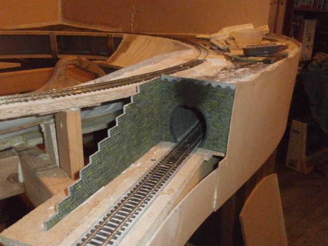

NEW STONE TUNNEL MOUTH
P2090075.JPG (173.63 KiB) Viewed 2269 times
NEW STONE TUNNEL MOUTH
P2090078.JPG (179.35 KiB) Viewed 2269 times
NEW STONE TUNNEL MOUTH
P2090077.JPG (174.25 KiB) Viewed 2269 times
NEW STONE TUNNEL MOUTH
P2090079.JPG (178.64 KiB) Viewed 2269 times
NEW STONE TUNNEL MOUTH
P2090080.JPG (177.54 KiB) Viewed 2269 times
timbologist
Posts: 372
Joined: Wed Sep 18, 2013 6:39 am
Location: Hazeldene Victoria Australia ( in the bush )

Re: MY NEW LAYOUT ARDUINO CONTROLLED

Post by timbologist »

Hi all
Had a busy weekend made a watering can in 1/12 scale for the Sister and Wife, have to keep the Wife happy :) .

Spent the rest of my play time working on a Tudor building I started 18 months ago, got side tracked.
It's big 16"long 5-1/2" wide and 8' high, walls are all 3d printed, roofs are plaster. The chimney is all 3D printed in pieces and glued together, and the fancy ironwork is 3D printed. Still got a fairway to go. The real chimney I believe is on Hampton Court.

Will put the photos of the whole building in another post.

Cheers
Tony
P2130018.JPG
P2130018.JPG (173 KiB) Viewed 2235 times
P2130017.JPG
P2130017.JPG (168.91 KiB) Viewed 2235 times
P2130016.JPG
P2130016.JPG (172.37 KiB) Viewed 2235 times
P2130015.JPG
P2130015.JPG (156.75 KiB) Viewed 2235 times
P2130014.JPG
P2130014.JPG (171.7 KiB) Viewed 2235 times
User avatar
End2end
Posts: 6010
Joined: Sun Jan 12, 2014 9:58 pm
Location: At the end....... and sometimes at the other end

Re: MY NEW LAYOUT ARDUINO CONTROLLED

Post by End2end »

:o VERY impressive chimnies! It's one part of houses I've always seemed to notice. Would it be possible for a top down view of the Barley? twist chimney please just to silence my inquisitve mind? :)
Also what mould is the the roof made from please Timbologist?
Thanks
End2end
"St Blazey's" - The progress and predicaments.
Welcome‎
Planning
Building
St. Blazey's Works & Depot thread
timbologist
Posts: 372
Joined: Wed Sep 18, 2013 6:39 am
Location: Hazeldene Victoria Australia ( in the bush )

Re: MY NEW LAYOUT ARDUINO CONTROLLED

Post by timbologist »

End2end wrote::o VERY impressive chimnies! It's one part of houses I've always seemed to notice. Would it be possible for a top down view of the Barley? twist chimney please just to silence my inquisitve mind? :)
Also what mould is the the roof made from please Timbologist?
Thanks
End2end
Top view of chimney as requested

The roofing is made from Linka mould R2 Standard Rough Shingle Roof Tile Sections, End Sections.

And just for you this is the roof under that Barley Twist Chimney, This roofing was made from a mould that the pattern was made on my 3D printer and I made a latex mould from it. Print once cast many :) .

Before you ask you can get this mould from here http://www.linkaonline.co.uk/store/p106 ... Mould.html. As I sent a pattern over, so this mould is available in the UK. I made a number of the patterns that are available as moulds at Linkaonline.

Cheers
Tony
TOP VIEW OF CHIMNEY
TOP VIEW OF CHIMNEY
P2140023.JPG (154.21 KiB) Viewed 2211 times
LINKA R2 MOULD
LINKA R2 MOULD
P2140024.JPG (172.39 KiB) Viewed 2211 times
VICTORIAN ROOFING
VICTORIAN ROOFING
P2140025.JPG (166.79 KiB) Viewed 2211 times
User avatar
End2end
Posts: 6010
Joined: Sun Jan 12, 2014 9:58 pm
Location: At the end....... and sometimes at the other end

Re: MY NEW LAYOUT ARDUINO CONTROLLED

Post by End2end »

Thanks for the additional info Timbologist.
timbologist wrote:I made a number of the patterns that are available as moulds at Linkaonline.
Can I ask, did you design the new platform moulds and curved paving sections as I am thinking to use them to build my platforms but wonder wether they are the correct radius / dimensions to sit either side of a double 2nd /3rd radius double track at setrack spacing?
If they do it means I can use LINKA to scratchbuild my whole station. :D
I'm yet to ask on the website but seeing as wer'e on the subject I thought I'd ask. ;)
Thanks
End2end
"St Blazey's" - The progress and predicaments.
Welcome‎
Planning
Building
St. Blazey's Works & Depot thread
User avatar
End2end
Posts: 6010
Joined: Sun Jan 12, 2014 9:58 pm
Location: At the end....... and sometimes at the other end

Re: MY NEW LAYOUT ARDUINO CONTROLLED

Post by End2end »

Thanks for the reply Timbologist. Sorry I wandered off....to make more LINKA tiles. :D
Yes it the stone platforms I was looking at. Nice job by the way. :)
I'll get over to the website to discuss the curved paving to see if it fits the width of the platforms.
God knows how I will bend the wall underneth to the same radius. :shock:
Maybe I will just do small pieces and work to the vertical rather than the horizontal or bend a piece of card to the correct radius and work off of that.
Thanks
End2end
"St Blazey's" - The progress and predicaments.
Welcome‎
Planning
Building
St. Blazey's Works & Depot thread
timbologist
Posts: 372
Joined: Wed Sep 18, 2013 6:39 am
Location: Hazeldene Victoria Australia ( in the bush )

Re: MY NEW LAYOUT ARDUINO CONTROLLED

Post by timbologist »

End2end wrote: God knows how I will bend the wall underneth to the same radius. :shock:
Maybe I will just do small pieces and work to the vertical rather than the horizontal or bend a piece of card to the correct radius and work off of that.
Thanks
End2end
There is a couple of ways that I have attacked the curved tiles problem.
!. Cast in body filler which is a type of plastic, can be carefully heated up carefully with a Hair drier after taking out of mould and formed to shape.
2. Make a Sandwich former to the radius you require allowing for thickness of mould, inside or outside curve.

Below is link to a tutorial on this and the results to give you an idea on how I have done it.
http://www.linkaonline.co.uk/02-making- ... casts.html

One thing to remember with curved stations is the amount of clearance you will need because of the swing of the rolling stock, You need to check all your rolling stock to make sure it will clear. That I found out the hard way :oops: I checked some of mine and of course the ones I did not check fouled, so out with the file to reshape it all :)

Tony
User avatar
End2end
Posts: 6010
Joined: Sun Jan 12, 2014 9:58 pm
Location: At the end....... and sometimes at the other end

Re: MY NEW LAYOUT ARDUINO CONTROLLED

Post by End2end »

Thanks for the tips Timbologist. :)
Thanks
End2end
"St Blazey's" - The progress and predicaments.
Welcome‎
Planning
Building
St. Blazey's Works & Depot thread
timbologist
Posts: 372
Joined: Wed Sep 18, 2013 6:39 am
Location: Hazeldene Victoria Australia ( in the bush )

Re: MY NEW LAYOUT ARDUINO CONTROLLED

Post by timbologist »

Hi all

The weekend started a new sheet mould from Linka Brick tiles making a sheet 3 rows, 96mm high and 6 columns 192mm wide.

First photo is the tiles as they will go together making sure all the tiles are the right way up.
The second photo shows all the tiles marked with arrows showing which way is up, ( and I got it right :) )
Third photo is the tiles clamped in the jig ready to glue together, the extra end tiles are to keep the tiles together. Now gluing together as with others recently been playing with methods to put together,
My preparation is to file all 4 sides first, then file the fingers, I file the fingers tapered front to back larger at front, and tapered thinner to there ends. This ensures that the front faces of the joins sit together as good as possible.
Now the glue that I use is my own mix, consisting of ABS, Acetone and Baby Powder. The mix is very thin and wicks down through the joint to the front face, usually requires a couple of goes to fill the gaps as it goes down into the gaps.
When dry sand back flat then coat with 1 pound cut of Shellac, turn over and stick to sheet of glass using double sided tape. Fill the gaps on the front side with same mix, when dry sand of flat then re-cut the grooves, where needed patch up the holes. When all finish coat with 1 pound cut of Shellac ready to make the mould.

Timbologist
loose tiles layout front
P2190034.JPG (167.79 KiB) Viewed 2052 times
loose tiles from back
P2190035.JPG (160.99 KiB) Viewed 2052 times
tiles held in place in jig
P2190036.JPG (165.63 KiB) Viewed 2052 times
tiles glued and filed ready to make mould
P2200038.JPG (172.14 KiB) Viewed 2052 times
Post Reply