Back to N...Under construction. Building Bridges.

Post pictures and information about your own personal model railway layout that is under construction. Keep members up-to-date with what you are doing and discuss problems that you are having.
User avatar
Zunnan
Posts: 1208
Joined: Mon Dec 03, 2007 2:54 pm
Location: On the cusp of spaghetti...B23

Back to N...Under construction. Building Bridges.

Post by Zunnan »

No I'm not swapping and changing my mind, Canon Streets stock has been sitting in boxes for closing in on 2 years, I really do need somewhere to be able to stretch their legs and keep everything in working order. I also need somewhere to be able to stow away the four 2' x 4' baseboards for the OO DCC layout. What I'm thinking is to produce two 'chest of drawers' with each to hold two baseboards, so each chest will need internal dimensions of 2' x 4' by 3' high to house the boards. This in turn leaves me with a potential 2'2" x 8'4" workbench surface that is surplus to requirements; perfect dimensions for some N Gauge fun! :wink:

I'm thinking continuous run, with a twist. A classic dog bone trackplan twisted back on itself giving me 2 passing loops long enough to hold full length trains and allow a train to pass on each reverse loop. Now, a reverse loop in N takes up about 2' x 3', so that leaves a scenic section of just 2' x 5' or there abouts, and I don't like visible tight curvature so that cuts another 12" off the scenic run. Add into the mix that the reverse loops will need to be stacked on top of each other to save space means that the entire visible running line will need to be on a ruling gradient of 1:60 in order to meet the 50mm clearance required for the loops to sit one on top of the other. Quite the challenge, eh?

So the plan, this is the basic idea:

Image

The problem I have with this plan is that the passing loop for the industrial sidings completes a reverse loop. However if I were to remove the crossing, bottom left, and just have the passing loop feed off the inner line, then there is no reverse loop on the layout at the expense of operational flexibility. To be honest, I'm not too fussed about that being as the yard spills directly into the upper storage loop, and that alone can soak up a lot of train movements to/from the yard. The alternative is some complex switching for DC to govern the yard feeds or two storage loops, or to convert to DCC and use a reverse module on either the entire yard, or a module for each of the loops. Personally, I think it would be easier to omit the crossover.

Any thoughts?
Last edited by Zunnan on Wed Mar 09, 2011 9:12 pm, edited 6 times in total.
Under Construction N Gauge dog bone.
Canon Street. N Gauge
The Workbench.
m8internet
Posts: 1640
Joined: Mon May 15, 2006 7:32 pm
Location: Cumbernauld, Scotland

Re: Back to N...

Post by m8internet »

24" with a 1:60 gradient for one level at 50mm
Are you sure your maths is right?
Also your diagram has an inner track so the width is going to be vastly less than 24" and so the gradient ratio will be vastly larger

I have recently completed a helix which is slightly wider
The level is 60mm but the gradient works out at between 1:30 and 1:45 (due to there being four parallel tracks, the inner track at 1:30 and the other outer track at 1:45)
Glasgow Queen Street Model Railway layout : modern image N gauge using DCC
User avatar
Zunnan
Posts: 1208
Joined: Mon Dec 03, 2007 2:54 pm
Location: On the cusp of spaghetti...B23

Re: Back to N...

Post by Zunnan »

The maths is based on the length of the double track running lines on the scenic section, which is 4' long straight running plus the second/third radius 180 degree curve. Allowing 10 1/4" radius for the inner line gives approx 2'9" of length in addition to the two 4' straights, a total of 10'9" to fit in a 50mm rise. 1:60 should be more than possible, although I may well increase it to 1:50 to allow the double slip and part of the passing loop at the yard entrance to be on the level.
Under Construction N Gauge dog bone.
Canon Street. N Gauge
The Workbench.
m8internet
Posts: 1640
Joined: Mon May 15, 2006 7:32 pm
Location: Cumbernauld, Scotland

Re: Back to N...

Post by m8internet »

50mm is fine if there is nothing under the baseboard
However have you taken into account the frame and point motors that the lower level has to pass under?
I reckon you will be nearer 80mm

I've redone the calculations from the numbers you supplied above, and I get a gradient of 1:10
Thats MEGA steep!
The lower level to the upper level, from the start of the curve to the end of the curve
Even though you are suggesting the gradient starts further back on the straight, it won't clear the underside of the upper curve
Glasgow Queen Street Model Railway layout : modern image N gauge using DCC
Terrier

Re: Back to N...

Post by Terrier »

I like the circular storage loops, great use of space and options for variable train movements. Also warm to the warehouse/works area, imagination can run wild with the area there. good plan Zunnan. :)
User avatar
Zunnan
Posts: 1208
Joined: Mon Dec 03, 2007 2:54 pm
Location: On the cusp of spaghetti...B23

Re: Back to N...

Post by Zunnan »

At 1:60 the track will rise to approx 19mm along the back edge of the layout before it reaches the first curve, it will then rise a further 12-13mm through the curve from beneath the warehouse to a road overbridge, leaving another 19mm required for the 4' through the passing loop. Given that 1:60 is 5mm rise per foot, a 10'9' run should give a possible maximum climb of 54mm. This plan doesn't use a helix by the way, which is where I think you're going adrift with the gradient calcs. The gradient runs between the double red lines along the 'U' shaped part of the layout, not through the loops; these are level and not connected.

50mm may well be tight, but I have a cunning plan which I've seen used in helix construction to compress the space required and also negate the need for bulky framework. I've measured a few locos on code 80 rail and they stand 32mm high in total, assuming a 9mm ply trackbed this should leave 9mm clearance. As the loops are storage, not scenic, it is planned to use surface mounted point motors rather than to mount beneath the track which greatly reduces the need for space. If desperately required, I have the leaway to increase the clearance to 60mm and still be able to keep the gradient within 1:50, which should allow for a max 65.5mm in the distance available.
Under Construction N Gauge dog bone.
Canon Street. N Gauge
The Workbench.
m8internet
Posts: 1640
Joined: Mon May 15, 2006 7:32 pm
Location: Cumbernauld, Scotland

Re: Back to N...

Post by m8internet »

Zunnan wrote:I have a cunning plan which I've seen used in helix construction to compress the space required and also negate the need for bulky framework
I agree, if your helix is layered or your baseboard is thin sections, then no supporting framework is required
You then simply have to consider the space available, between the top of the lower baseboard and the bottom of the upper one
Personally I am using 75mm
That leaves enough room for the track, rolling stock on top, and then a fingers width, just in case access is required
If access is limited then I increase this gap to 150mm (which is the height my helix uses)
This then allows an arm between the top of the rolling stock and the bottom of the upper baseboard
Glasgow Queen Street Model Railway layout : modern image N gauge using DCC
User avatar
SouthernBoy
Posts: 1753
Joined: Sun Oct 08, 2006 11:01 pm
Location: The past: We do things differently there

Re: Back to N...

Post by SouthernBoy »

Nice and inventive Zunnan - and glad you've found a way to get back into N gauge :)

One thought:
On my previous layout I found the gradient on curves needed to be less than on straights, otherwise trains slowed quite obviously on the curves.
I experimenting with varying the degree of gradient between straight and curved sections until trains ran at reasonably constant speed throughout.

Anyway - good luck :)
User avatar
Zunnan
Posts: 1208
Joined: Mon Dec 03, 2007 2:54 pm
Location: On the cusp of spaghetti...B23

Re: Back to N...

Post by Zunnan »

I found with Canon Streets 1:35 on a tight curve that only the longest trains (8+ coaches, 30+ wagons) were seriously affected. Due to the constraints of the storage yard, I have found that the longest trains will be about 7 coaches in length, this length should fill the inner siding on either loop and from experience with Canon Street, a 1:60 or even 1:50 gradient should be workable with very little fuss. Well, I say 7 coaches, I checked with 3 cargowagons and a Peak so it could be 8 Mk1s and a short locomotive perhaps :lol:

I've just returned from my local model shop (HobbyRail) having forked out for the storage yard track, and it cost me less than it would from the box shifters. Not to mention a staple 1980s and early 90s Black Country workhorse for steel workings (class 31), also cheaper than certain box shifters knock them out for! The omens are so far looking good for this one, although I was only supposed to be pricing it up and buying the woodwork first. Looks like construction of the OO storage boxes will have to wait a couple of weeks now... :roll: :lol:

On another positive note, I think I've solved the reverse loop issue for either DC or DCC running with the passing loop.

Image

The area shown in red is basically what will potentially cause a short. My options are isolate this area entirely and switch the track feeds independantly, or just remove the problematic point and crossover and have the passing loop fed off the inner line at both ends. I am at the moment favouring isolation, purely on the grounds of operational flexibility. For DC it will probably require a DPDT switch, likely governed by the points on the outer line to make the passing loop live to the outer line only when routed to do so, and then another manual DPDT to switch between running line feeds and the yards feed for shunting purposes. DCC would just require a reverse module for the red area I presume, given that the outer line and inner lines feeds are reversed (due to the storage loops) and the yard would have the same feed orientation as the inner loop.

Can anyone see any problems with either approach that I have missed?
Last edited by Zunnan on Wed Mar 09, 2011 9:12 pm, edited 3 times in total.
Under Construction N Gauge dog bone.
Canon Street. N Gauge
The Workbench.
m8internet
Posts: 1640
Joined: Mon May 15, 2006 7:32 pm
Location: Cumbernauld, Scotland

Re: Back to N...

Post by m8internet »

I can't see a red area, there is enough contrast with the black for me to see it

Have you taken into account that when using a reversing loop it needs to be no shorter than your longest train?
Glasgow Queen Street Model Railway layout : modern image N gauge using DCC
User avatar
Zunnan
Posts: 1208
Joined: Mon Dec 03, 2007 2:54 pm
Location: On the cusp of spaghetti...B23

Re: Back to N...

Post by Zunnan »

I'll edit the image to make it stand out better, its just the passing loop that is highlighted anyway. :)

As its effectively a dead end, I don't think train length should be really affected unless something runs wrong line into the loop and out onto the running line at the other end, which is why the headshunts are shaded too, and its physically impossible to run directly from outer line to yard, hence it will be wired such that the yard is fed the same way round as the inner line.
Under Construction N Gauge dog bone.
Canon Street. N Gauge
The Workbench.
0121modeller
Posts: 1205
Joined: Sun Mar 09, 2008 1:16 am
Location: Erdington, Birmingham,.... but can also be found at various railway bridges !

Re: Back to N...

Post by 0121modeller »

Zunnan wrote:I've just returned from my local model shop (HobbyRail)
Zunnan wrote:although I was only supposed to be pricing it up and buying the woodwork first. Looks like construction of the OO storage boxes will have to wait a couple of weeks now...
Hey Zunnan :D ,likewise, I visited hobbyrail today also as it happens :lol: , I also, only meant to buy bits of track & a "castle cement" wagon by farish, he had 3 in stock at a good price, so i snapped them up too.
I think i know which 31 you had, the railfreight grey one ? I had my eye on that one too ! , Although I've already one similar.

Also, I too need too get the woodwork, was going to buy this today, but then decided its best to work on a trackplan first as i have a similar available space of 8ft x 2ft 6".
Looks a great plan you're designing, I like the idea of multi level, gives a reason as to build girder bridges :)
What sort of passenger trains are you intending to run ?

I will be following this project as to maybe steal a few idea's & learn from your extensive knowledge :wink: .
I'll need to find out about that XtrackCad track design thingy,... i've only ever used pencil & grid referance paper / and trial & error methods before.

Cheers :) ,
Dave.
Scratchbuilding 4mm scale JXA scrapwagons ; - http://www.newrailwaymodellers.co.uk/Fo ... =6&t=37620
Scratchbuilt & kit built grappler claw cranes ; - http://www.newrailwaymodellers.co.uk/Fo ... =6&t=36342
User avatar
Zunnan
Posts: 1208
Joined: Mon Dec 03, 2007 2:54 pm
Location: On the cusp of spaghetti...B23

Re: Back to N...

Post by Zunnan »

The main reason behind the layout is to get Canon Streets stock out of the storage boxes, run it and keep it maintained. That means a distinct bias towards the transition era, but as you noticed there is a Red Stripe 31 missing from the shelf in the shop. I really do need to exercise some restraint on those impulse buys! :lol:

The era for the layout is intended to be switchable from 1960 to 1990 (give or take), as per my initial plans for doing Griff in OO gauge, passenger trains are covered for the transition period by a pair of class 101s (2+3 car) and a loco hauled Suburban rake for local services. Then I have a raft of Mk1, Stanier and Gresley stock to make up any length and formation for longer distance stoppers and expresses. To bring it into the '70s I'll need blue 101s, 108s and 121s. Mid '80s onwards will need 150s and 156s with older units thrown in. I'm waiting on the new Farish Mk1s before getting any Blue/Grey coaching stock, but I also want early Mk2s and Aircons to be able model the Northeast/Southwest cross country trains of the '70s and '80s...and maybe a HST or two, one in blue/Grey, the other in a mix of Exec and Blue/Grey. Looking at my wants list, I think I'd better expand the storage yards with a 4th loop each! :shock:

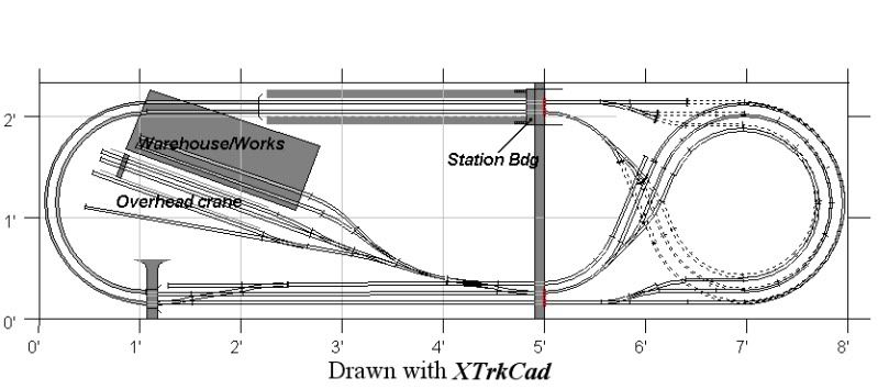
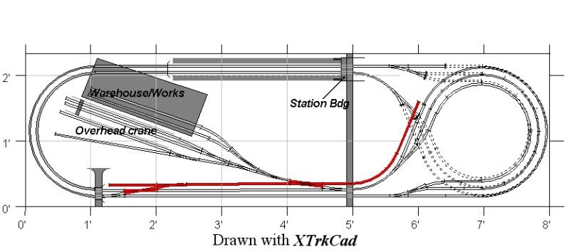
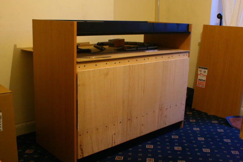
Ever since building Canon Street, I don't think I could build a flat layout ever again, even the OO layout isn't flat. Although the track plan is all level, the ground level is above and below this. Definately plan in advance of doing the baseboards, multi level layouts only work with quite a bit of planning, otherwise you can end up with a flat tabletop railway with 1:5 gradients trying to get up to that terminus station you wanted but couldn't fit in any other way. I always start with a pencil doodle on scraps of paper, and a few scribbled calculations thrown in where gradients are involved. XtrkCad comes after the paper has provided a potentially workable idea, mostly because its easier to get an idea of what the available points will let you get away with in a given space; if i were better at getting point profiles right, I'd stick to pen and paper! :lol:

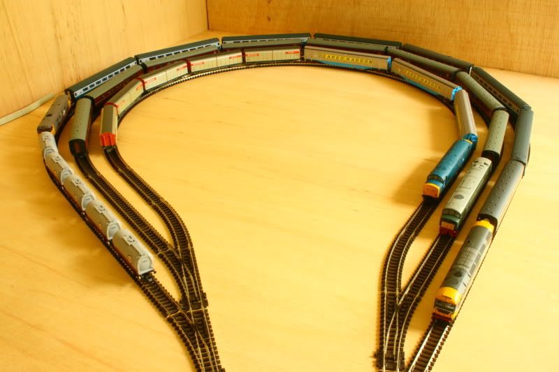
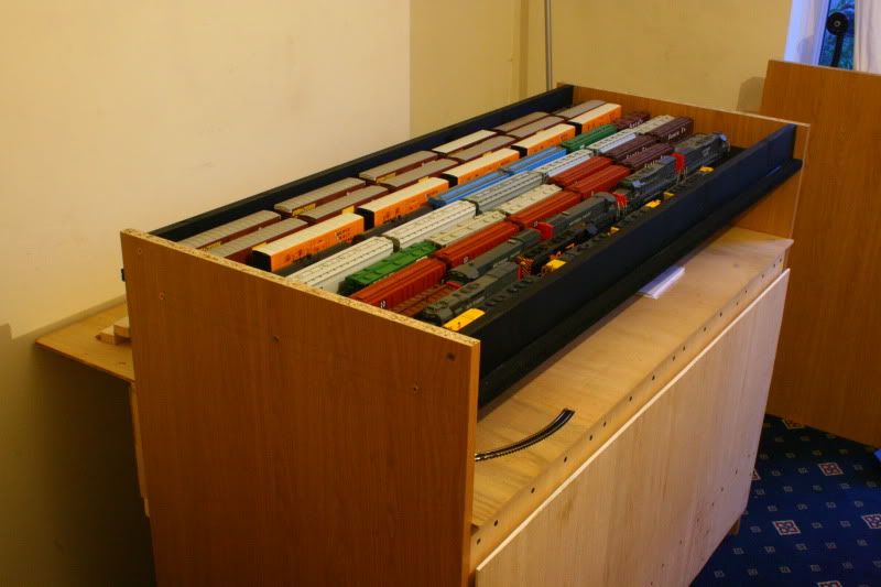
Edit ~ Being as I have the track to do it, I decided to mock up the upper storage loops in their entirity. Mainly to check clearances between the lines using long vehicles with large overhangs (class 44 and cargowaggons), but also to gauge the capacity of the yard and confirm the XtrkCad dimensions.

Image

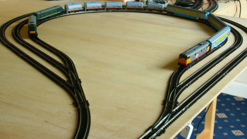
The first radius loop comfortably holds a decent amount of stock. 8 Mk1 coaches and a Peak just fits in if one of those Mk1s is a BG which suits me for a layout of this small size, thats longer than the station can hold and means that the inner loops can comfortably be used to hold 2 or 3 DMUs each. The other two loops obviously will hold more quite easily. So, how accurate was XtrkCad? Not far off at all to be honest. When I measured the loops as laid out, they come in at 36 1/2" long and 25" wide which is only 1/2" off what the plan states. I think I'll have the right hand headshunt extend around the outside of the upper loop to accomodate a full length train rather than having it at just over half of this length as currently shown on the plan, and also provide a 4th radius loop on the lower level loop. There should be enough room for these changes to work.
Last edited by Zunnan on Wed Mar 09, 2011 9:13 pm, edited 1 time in total.
Under Construction N Gauge dog bone.
Canon Street. N Gauge
The Workbench.
User avatar
Zunnan
Posts: 1208
Joined: Mon Dec 03, 2007 2:54 pm
Location: On the cusp of spaghetti...B23

Re: Back to N...

Post by Zunnan »

A full capacity check on the storage loops has now taken place running on DC with the track temporarily laid on the OO layout to complete a circuit. I think its safe to say that they work, and they happily hold full length trains. The only issue that I have is that Farish VGA vans can't use the middle road because they don't like the reverse curves on the exit pointwork. If I used streamline points they would be fine, but that would sacrifice capacity. However, they do run happily on the 9" radius inner loop, so at least they can be parked up 'off stage' on the loops rather than ran around then shunted back into the yard to get them out of the way.

Image

I think that initially I'll wire it for DC operation being as none of my stock is DCC fitted and theres loads of it to convert, but it will be build in such a way that DCC conversion will simply involve joining the droppers to a common BUS wire or reverse module(s) as required. Planning and initial testing done, let construction commence when I've been paid...
Last edited by Zunnan on Wed Mar 09, 2011 9:13 pm, edited 1 time in total.
Under Construction N Gauge dog bone.
Canon Street. N Gauge
The Workbench.
User avatar
Zunnan
Posts: 1208
Joined: Mon Dec 03, 2007 2:54 pm
Location: On the cusp of spaghetti...B23

Re: Back to N...Now under construction!

Post by Zunnan »

The foundations for the baseboards are now going from the planning stage to the 'bigger than I expected in reality' stage. The idea is to build a 'chest of drawers' to store the 8' x 4' 00 gauge layout in, where the drawers are actually the modules which form the layout. I have built the first chest to test that this will actually work, and have to say that its a bit bigger than I was expecting standing a meter tall with a 4'2" x 2' footprint! Still, that means the N Gauge layout on top has a new total area to play with of 8'6" x 2'6" or there abouts and will be a bit higher than I originally envisaged.

Image
This shows the built chest complete with two boards from the 00 layout inserted (one with the trial N Gauge storage loops still in situ). Construction is simple, there are two 4' x 2' 18mm boards braced with 18mm x 70mm timbers, these form the top and bottom panels to the chest and are sealed with acrylic car paint which renders it entirely waterproof to the point that it can be submerged in a bath with no ill effects (as well as avoiding using naff varnishes :wink: ). The sides are formed using 18mm thick 'conti board', the stuff flat pack furniture is made of, and have a timber runner fitted to them. The whole assembly rides on castor wheels to make a versatile and mobile construction. Rigidity of the structure actually comes from the layout itself, but it is sturdy enough without the layout 'drawers' inserted.

Image
An added bonus to the design is that the top of the chest can be used for storage. For those too lazy to count as well as a graphic of just how large these are, there are 42 American H0 freight cars and 10 diesels in the top tray plus 16 square feet of scenic 00 layout and an N Gauge test layout in the lower storage section. Of course, there will be a layout going on top of the tray, but I am giving serious consideration to hinging the layout at the rear to give ready access to the electrics. This will then mean that the 'temporary' tray formed by the bracing of the chest then becomes actual storage space even when the N Gauge layout is in place.

Huge vets bills this month means that only the two chests can be built for now, but that will also give me plenty of time to ponder exactly how to mount the N Gauge layout on top of the two chests.
Last edited by Zunnan on Wed Mar 09, 2011 9:14 pm, edited 1 time in total.
Under Construction N Gauge dog bone.
Canon Street. N Gauge
The Workbench.
Post Reply