OO. DCC. Setrack....Canon Dale Colliery

Post pictures and information about your own personal model railway layout that is under construction. Keep members up-to-date with what you are doing and discuss problems that you are having.
User avatar
Zunnan
Posts: 1208
Joined: Mon Dec 03, 2007 2:54 pm
Location: On the cusp of spaghetti...B23

OO. DCC. Setrack....Canon Dale Colliery

Post by Zunnan »

It's been about 8 months since my N Gauge layout had to go into storage, tinkering with bits and pieces just hasn't been scratching my itch and house sharing hasn't given me the room to do much else. I've given up (for now) trying to buy somewhere but have moved into a fairly roomy house which I can now sprawl my clutter all over. Canon Street isn't on the menu yet, I want to think long and hard about that as I have big (expensive) plans for that. But what I do have is an abundance of OO stock which hasn't ever seen a layout as I continue to stockpile for the layout I want to build that'll last me a lifetime (Griff Junction)

Arise Canon Dale Colliery!

Thanks to layouts by the likes of smallman28 and MrT, the decision was made some time ago to build a tail chaser using the track from my abandoned DCC project and build it to as high a standard as I can muster. Until now I just haven't had the space to do so. During my house move I found a plan I had drawn and not completed some 15 years ago, so I decided to do the honourable thing and end its lament by actually building it rather than throwing it away...My apologies for not using xtrkcad, but I'm not using it for this layout, I'm working from a crusty old sketch :P
Image

To check that the track plan was feasable, I laid out the remnants of my DCC project on some sheets of ply and had a play around with clearances. The plan had numbers relating to setrack radii on most of the curves, 2nd radius minimum on the inner running line, which I wasn't so keen on, so first off I altered that to 3rd radius and 4th radius. I also added in a second crossover so that the sidings at the rear of the plan were workable from both lines without having to reverse trains over a curved crossover which resulted in the following ~
Image

More than surprised at the comfortable fit, it has now become all systems go. Because this is essentially a setrack layout, I want to make this look as uncluttered as possible while squeezing as much as I possibly can to make what is a small tailchaser operationally interesting. It is essentially a flat layout, and I have made open frame boards in the past to accomodate ground level changes, so for this I am going to go the whole hog! Not only that, the layout will need to be portable in case I have to move so it is going to be semi open framed and modular, with the intention that it can also be extended if I want! I opted for exhibition style entirely ply construction, 'egg box' baseboards for their lightweight and handy portability. The 8' x 4' layout will require four 4' x 2' baseboards, each being made from 6mm ply 'timbers' on a 12" x 12" framework for strength and rigidity and a 9mm ply top. The next series of photos show the skeleton of the first board as it is built.

Image
The spine of the box assembled. Not very strong, in fact it was incredibly flimsy, there is nothing to hold it together yet. At this point I questioned my sanity in opting for this design of board.

Image
The board edges were fixed in place and the land profile below rail height cut well clear. A slab of loft insulating board was cut to shape and inserted in the corner. Already the box was getting stronger.

Image
Image
The 9mm ply top was offered up to check the fit and all was level before fixing into position, and the rest of the loft foam was cut to shape before the board top was glued and screwed into place. If you check back the the plan, you can see how the seperate piece of foam will form the road which runs from the overbridge to the underbridge when it has also been carved out. I can confirm that this board when supported between two chairs will hold my bodyweight (only 12 1/2 stone...) comfortably with no sagging.

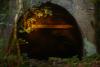
At this stage I got a little bored of woodwork and decided it would be more fun to get some trains out and have a play with photographic angles for the finished article...So back out with the track and I also carved the embankment roughly into shape. Some photos of my little indulgence ~

A pair of 47's on, err, 'clearance rechecking'.
Image

Image

Image

A 37 backing it's train into the colliery to be loaded for domestic use (hence the use of HEA's)
Image

37 254 runs light engine back to the colliery after refuelling at the small depot a little further down the line.
Image

At this point I decided to keep the track out and lay it properly, so out came the cork underlay and the soldering iron for doing a little DCC DIY on the points. Hornby provides those horrible little staples to make their points all live, and as I prefer to use Peco track, I decided to go about things in a more permanent way so as to bypass those flimsy little contacts on the point blades. My apologies, I photographed that process too :lol:

Image
The sleeper webs were cut just behind the point blades so I could gain access to the bottom of the rails.

Image
Using some 0.5mm bare copper wire (as used on telephone lines) I electrically bodged the rails together. I used 0.5mm single strand with DCC here as it is sufficient as an emergency backup should the point blade contacts fail, and is easier to disguise than heavier duty wire. Being as I am providing a lot of track feeds via a 4mm bus and 1mm droppers, they'll never need to carry much current as there will always be a path of lower resistance.

Image
Naturally before I laid the point on the layout, I made sure that it was electrically sound so as not to cause any shorts when in operation.

Image
Also before laying, the copper links were resin coated for protection and painted to match the sleeper colour. From above they are quite discreet I think you will agree, and easy to hide when ballasting begins. :)

Image
Image
While I was at the track laying game on this board, I also soldered the droppers on to the rail joiners so they too could be hidden effectively. On this first board there are no less than 5 track feeds, one at each end of the circuits, and one for the headshunt. This is the first time I've bothered to attempt to hide the track feeds, and even in this under construction state, I can say I'll never solder a track feed to the side of a rail ever again!

Now that this board is pretty much complete in terms of tracklaying and basic electrics (well, the bus is still needed, as well as linkages to adjacent boards and point motors...) my focus for the weekend is going to be on building the board for the colliery itself. This board will include a 5 arch bridge with later built girder bridge extension built to accomodate a road realignment for the colliery, the exchange sidings, loading plant and a disused canal wharf (if it fits between the exchange sidings and the running lines...). Nothing like a woodwork challenge to keep you occupied is there?! :lol:
Last edited by Zunnan on Tue Aug 04, 2009 7:48 pm, edited 1 time in total.
Under Construction N Gauge dog bone.
Canon Street. N Gauge
The Workbench.
boyofbears
Posts: 189
Joined: Fri Aug 17, 2007 3:21 pm
Location: bucks

Re: OO. DCC. Setrack. 3 things I never thought I'd work with.

Post by boyofbears »

hi,

i se you have thought this through!

it all looks very tidy and i like the plan, wish i had done my boards like this!

i will be watching this progress with interest.

Oak
my imaginery friend thinks u have problems.......wait........
my layout http://www.newrailwaymodellers.co.uk/Fo ... 22&t=17368 new!!!
User avatar
mattmay05
Posts: 1991
Joined: Wed Dec 12, 2007 4:16 pm
Location: Isle Of Wight
Contact:

Re: OO. DCC. Setrack. 3 things I never thought I'd work with.

Post by mattmay05 »

Nice start, be watching to see how it develops good luck, keep up the good work. :D
- Youtube/bluebellModelrailway
- https://railway-modeller-mw.weebly.com/
- VECTIS 3D: mademe.co.uk/shop/vectis-3d-models/
ste234
Posts: 957
Joined: Wed Feb 18, 2009 10:02 pm
Location: Teeside

Re: OO. DCC. Setrack. 3 things I never thought I'd work with.

Post by ste234 »

OO, Setrack, how dare you :lol: :wink:
Looks good i like the frame work, i never thought of doing anything like that :roll:
Keep it up :D
Ste. :)
'Springfield', N gauge Modern Era Layout
hobby boy
Posts: 429
Joined: Sat Mar 14, 2009 8:22 am
Location: Basingstoke, Hampshire, United Kingdom
Contact:

Re: OO. DCC. Setrack. 3 things I never thought I'd work with.

Post by hobby boy »

ste234 wrote:OO, Setrack, how dare you :lol: :wink:
Looks good i like the frame work, i never thought of doing anything like that :roll:
Well i'm also doing that!
Great start, if my layout was always going to be dcc, i would have done that!

Hobby Boy
I have this engine like the picture :) GWR 0-6-0 Pannier tank
Check out Andrew's layout Hookstoke Junction UPDATED! Should do more work as it's now the Easter Holidays :) After the holdiays are over, my layout won't get updated much Age = 15
User avatar
Spavo
Posts: 1274
Joined: Wed Sep 06, 2006 9:13 am

Re: OO. DCC. Setrack. 3 things I never thought I'd work with.

Post by Spavo »

Some excellent tips there especially the DCC points conversion, very nice.

Gav.
Watford FC For Me Since 1976
m8internet
Posts: 1640
Joined: Mon May 15, 2006 7:32 pm
Location: Cumbernauld, Scotland

Re: OO. DCC. Setrack. 3 things I never thought I'd work with.

Post by m8internet »

There is no need to solder the points, I have over twenty and no soldering anywhere!
Glasgow Queen Street Model Railway layout : modern image N gauge using DCC
Sprintex
Posts: 737
Joined: Tue Apr 24, 2007 6:54 pm
Location: No longer here
Contact:

Re: OO. DCC. Setrack. 3 things I never thought I'd work with.

Post by Sprintex »

Zunnan wrote:, I can say I'll never solder a track feed to the side of a rail ever again!
I never have. Much easier to cut away the webbing under the rail as you did for your link-wires and solder feeds to the UNDERNEATH of the rail, much easier to hide later and no fiddly soldering to rail-joiners :wink:


Paul
User avatar
Zunnan
Posts: 1208
Joined: Mon Dec 03, 2007 2:54 pm
Location: On the cusp of spaghetti...B23

Re: OO. DCC. Setrack. 3 things I never thought I'd work with.

Post by Zunnan »

m8internet wrote:There is no need to solder the points, I have over twenty and no soldering anywhere!
They're a failsafe more than anything. I have in the past had erratic point blade contact, and this layout is as much about belt and braces as it is about being as detailed as possible. The amount of track feeds alone should negate the need to wire the points, I agree that they're not needed at all if a layout is wired properly. Wiring wise for this layout, they are complete overkill :) On a true setrack layout which has only one or two track feeds though, I'd say they're essential for DCC to combat the number of potential bad joints in sectional track, which is part of the reason Hornby provide those little metal clips as well as to make sidings permanently live. I'd almost certainly use them for electrofrog pointwork and cut the switch rails electrically from the frog to produce a true electrofrog, again removing the need for point blade contact thus increasing reliability and reducing the risk of shorts.
Sprintex wrote:I never have. Much easier to cut away the webbing under the rail as you did for your link-wires and solder feeds to the UNDERNEATH of the rail, much easier to hide later and no fiddly soldering to rail-joiners
I'm used to N Gauge, soldering to rail joiners is far from fiddly! :wink: Besides, the flexibility of being able to lay the rail, fix it down, then drill the holes at the rail ends persuaded me to do it this way rather than directly to the rail itself, just in case the rail has to move before its fixed in place. This way, the wiring is the last thing to be added to the track section rather than being something to consider during laying. It's less for me to think about and I consider myself lazy when it comes to thinking while I'm doing something. Another good reason is that two of the curved points need moving as Heljan class 58's can't negotiate the curvature when the points are laid toe to toe (powered up the board and checked about an hour ago...not good), so some modification is needed to the track plan :evil: But on the plus side, the track feeds can stay where they are as it is just the track which needs to move and not the location of the joint! Hopefully a 3rd radius half curve between the point toes will do the trick.
Under Construction N Gauge dog bone.
Canon Street. N Gauge
The Workbench.
User avatar
Zunnan
Posts: 1208
Joined: Mon Dec 03, 2007 2:54 pm
Location: On the cusp of spaghetti...B23

Re: OO. DCC. Setrack. 3 things I never thought I'd work with.

Post by Zunnan »

The basic skeleton for the colliery board is now complete. I am separating the two sides of the board with a backscene, so the colliery occupies one half of the layout, and the station/depot occupies the other half, each with their own individual scenery. I have seen this done to great effect in articles from Model Railroader over the years and have yet to see it done on a compact British outline layout. What I should end up with is two separate scenic layouts in one where the common link is the road overbridge on the left of the plan.

Image
Basic skeleton with the below rail scenic sections cut out.

Image
9mm ply baseboard cut to shape. The hole in the centre will be occupied by the disused canal wharf, based on photos of Black Country coal wharfs as they were when the collieries closed...I hope I have left enough room. The canal will enter under the rail bridge on the 3rd or 4th arch with the wharf trailing back to the left, to the right will be a blocked off canal tunnel. At the extreme left will be the road under bridge which I am now trying to get an acceptable road profile on a bending 1:4.5 gradient using 6mm ply...This could take some time!
Under Construction N Gauge dog bone.
Canon Street. N Gauge
The Workbench.
User avatar
Zunnan
Posts: 1208
Joined: Mon Dec 03, 2007 2:54 pm
Location: On the cusp of spaghetti...B23

Re: OO. DCC. Setrack. 3 things I never thought I'd work with.

Post by Zunnan »

I've now got as far as I can on this months budget. The missing board front and end cut to shape and fixed in place, these aren't the finished articles, there will be a thin ply skin mounted over all the board ends profiled to match the topography. The road bed is shaped using 6mm ply as well as I can manage and also incorporates the footing for the rail bridge, which I have mocked up also using 6mm ply, seen here with a gratuetously posed class 58 hauling MGR empties to Canon Dale Colliery.

Image

What am doing now while I am twiddling my thumbs (needing more track, more cork and some 1"x1" timber to assemble the last two boards and to also construct the legs) is scrouging around in my bits boxes for some brick plasticard and building me a bridge. I've skinned the one side partly, the refuge points in the bridge parapet will be made from brass which I'm sure I have lying around somewhere, so I'll need to make up a small jig so I can produce enough near identical frames to complete the bridge.

Image
Skinned with plasticard.

Image
Arches cut out on one side, the next job here is to skin the other side and line the arches between them...oh, and also to cut the individual bricks to form the front of the arches. I did a single span arch last year this way and it took what seemed like an eternity to do. Now I have 10 similar arches to do.

Image
A pair of 20's on an empty MGR working pass a class 58 working in the opposite direction with a loaded MGR.

Image
The view under the road bridge. I am hoping that I have some plastruct somewhere to scratch build this part of the bridge, otherwise it will just have to wait

Image
The overview of the roadway and site of the bridges carrying the rails over the road.

I'm quite pleased with how much I have got done so far, feeling a little burned out from over modelling exposure so I may sit back and think about the other two boards for a couple of days. On the other hand, I might try and get as much of that bridge done as I can manage!
Under Construction N Gauge dog bone.
Canon Street. N Gauge
The Workbench.
zarniwhoop
Posts: 76
Joined: Mon Sep 17, 2007 7:05 pm
Location: Brighton

Re: OO. DCC. Setrack. 3 things I never thought I'd work with.

Post by zarniwhoop »

VERY interesting. You've obviously given a lot of thought to this, so how do you plan to support the boards, and fit them together ?

ĸen
User avatar
Zunnan
Posts: 1208
Joined: Mon Dec 03, 2007 2:54 pm
Location: On the cusp of spaghetti...B23

Re: OO. DCC. Setrack. 3 things I never thought I'd work with.

Post by Zunnan »

zarniwhoop wrote:VERY interesting. You've obviously given a lot of thought to this, so how do you plan to support the boards, and fit them together ?
The plan is to build folding legs into the end two boards on a sub frame which slots inside the 'egg carton', the inside edge will have a lip at the bottom which both the outer and one end of each inner boards will sit on so that they are held level. Reading this you will assume that the middle boards will have no support...and you'd be correct in this assumtion! As I mentioned earlier, I stood on the first board I made when it was suspended on two chairs, so the integral strength and relative light weight should mean that the middle boards should only need minimal support. This will be given by the leg sub assemblies for the outer two boards. Alignment will simply be via 8mm wood dowels and the boards will literally clip together using toggle plates.

Electrical linkage from board to board is going to be via 2 pin shaver plug/sockets, because this is DCC, there is only going to be one link ber board joint. Point motor control is another issue which I am yet to fully decide on, but I am at present envisaging din sockets and ribbon strip or 20 pair 0.5 telecomms cable, although I am toying with the idea of using SCART sockets and leads for ease of purchase of leads in the event of needing a replacement.

If all goes well, this layout should be dismantleable/erectable in under 10 minutes, which puts a lot of exhibition layouts to shame!
Under Construction N Gauge dog bone.
Canon Street. N Gauge
The Workbench.
User avatar
Zunnan
Posts: 1208
Joined: Mon Dec 03, 2007 2:54 pm
Location: On the cusp of spaghetti...B23

Re: OO. DCC. Setrack. 3 things I never thought I'd work with.

Post by Zunnan »

I thought I had some brass lying around, but no! Still, a couple of £ for some 1/8th 'L' section and some 0.75mm rod seemed like just the trick for what I needed, I think I can safely say an extra £2.50 on brass isn't going to bust the bank! I constructed a simple jig in a block of wood, 4 holes spaced 15mm apart horizontally and 6mm apart vertically and a slot cut 15mm below the top two holes to take the 'L' section. As usual, I photographed the process as this game of actually doing what I've been planning is all completely new to me, and I've never scratch built anything using brass before.

Image
The basic components which will make the refuge point railings. The 'L' section has had the ends slotted and bent in to form the toe boards, the railings bent at 90 degrees 15mm apart and two vertical rails to support everything.

Image
The railings and toe board inserted into the jig.

Image
The vertical rails moved in to position and soldered in place, one side at a time.

Image

Image
The finished article! It doesn't look much, but once mounted on the bridge sides, they will make all the difference!

Image
Making a jig really does help when batch building scratch built components! Once the railings and toe boards were all bent to the required shape, it took no more than 30 minutes to make all 8 refuge points; about 90 minutes work all in all, including making the jig.

So...how do they look when fitted to a bridge side? I'll let you be the judge of that! :D

Image

Image
As you can see there is still a lot to do before this bridge is finished, mainly in the arch linings, but also in covering up the joins between the 'Wills' plasticard sheets. Once the brick lining is complete, it will be time for painting into blue engineering brick with the typical grey railings you see on metalwork around the network.

Anyway...thats more than enough for tonight!
Under Construction N Gauge dog bone.
Canon Street. N Gauge
The Workbench.
boyofbears
Posts: 189
Joined: Fri Aug 17, 2007 3:21 pm
Location: bucks

Re: OO. DCC. Setrack. 3 things I never thought I'd work with.

Post by boyofbears »

that,
is brilliant!
my imaginery friend thinks u have problems.......wait........
my layout http://www.newrailwaymodellers.co.uk/Fo ... 22&t=17368 new!!!
Post Reply